Interactive Raytracing: The nirt Command
The nirt command casts individual rays according to user-specified
options, and reports back a wide variety of information about the
model along the specified ray. It is extremely useful for tasks such
as measuring the thickness of objects and identifying gaps between
objects. When used within the MGED environment, NIRT will produce a
visible ray path, coloring the ray according to the geometry
encountered along the ray. It is also scriptable, allowing users to
develop their own custom analysis routines.
1. About NIRT
The NIRT (Natalie’s Interactive Ray-Tracer) command line tool
provides a user-level interface to the low-level routines defining the
ray tracing logic, allowing a user to specify and cast an individual
ray and tailor the information reported. It was originally written by
Natalie L. Eberius and Paul J. Tanenbaum in the early 1990s, with
additional updates by others over the years. Significant work was
done by Bob Parker in the late 1990s to integrate NIRT with
MGED, resulting in wireframe visualization of ray paths and the
Query Ray Control Panel.
2. NIRT: Basic Syntax and Operations
There are two environments within which NIRT can be used -
inside the MGED interactive geometry editor and within its own
command line interactive environment. Consequently, there are three
command line environments where behavior needs to be described in this
document; operating system command prompt, NIRT command prompt,
and MGED command prompt. The convention used here will be:
| Command Line Environment | Command Type |
|---|---|
Operating System Command Line Prompt |
command |
|
interactive command |
|
|
2.1. Command Line Help
NIRT provides an h option which prints out a list of
available options and command syntax:
user@machine ~ $ nirt --h
Usage: 'nirt [options] model.g objects...'
Options:
 -b        back out of geometry before first shot
 -B n      set rt_bot_minpieces=n
 -e script run script before interacting
 -f sfile  run script sfile before interacting
 -L        list output formatting options
 -M        read matrix, cmds on stdin
 -O action handle overlap claims via action
 -s        run in silent (non-verbose) mode
 -u n      set use_air=n (default 0)
 -v        run in verbose mode
 -x v      set librt(3) diagnostic flag=v
 -X v      set nirt diagnostic flag=v
2.2. Loading a Model
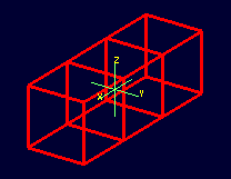
There will be a number of models used to illustrate various
NIRT behaviors, all of which will be centered around regions
created with various combinations of 2mm arb8 cubes. The left cube is
centered at (-2, 0, 0), the center cube at (0, 0, 0) and the right
cube at (2, 0, 0). One additional arb8 will be defined to overlap the
center cube with side lengths in the z direction of 4mm. The various
models based off of these primitives will be read from a database
called nirt_example.g.
NIRT behavior.Although there are many nirt options available, only the database
name and objects are essential to get started:
nirt model.g objects
where objects is a list of objects in the database separated by
spaces. To begin, select the object center_cube.r object with
interactive command line NIRT. The form of the command is:
[1]
nirt nirt_example.g center_cube.r
This starts up the NIRT command line interactive environment:
BRL-CAD Release 7.13.0  Natalie's Interactive Ray Tracer
    Tue, 26 Aug 2008 23:21:32 -0400, Compilation 2
    user@localhost:/usr/brlcad
Database file:  'nirt_example.g'
Building the directory...
Get trees...
Prepping the geometry...
Object 'center_cube.r' processed
Database title: 'Example BRL-CAD Database'
Database units: 'mm'
model_min = (-1, -1, -1)    model_max = (1, 1, 1)
nirt>
The first three lines identify the release number, tool being used,
date of compilation or date release was made, and user. The fourth
line identifies the database file. The next three lines are
informational messages relating to model setup. The database title
and units are then printed. The last pieces of information,
model_min and model_max, are the outer bounds of the objects
specified.
2.3. Shooting a Ray
With the example loaded into NIRT, the s interactive command
is used to shoot a ray:
nirt>  s
Origin (x y z) = (0.00000000 0.00000000 0.00000000)  (h v d) = (0.0000 0.0000 0.0000)
Direction (x y z) = (-1.00000000 0.00000000 0.00000000)  (az el) = (0.00000000 0.00000000)
    Region Name               Entry (x y z)              LOS  Obliq_in Attrib
center_cube.r        (   1.0000    0.0000    0.0000)   2.0000   0.0000
What happened and what do these results mean? The following table breaks down the structure of the report:
| Report Element | Meaning |
|---|---|
Origin |
Origination point of the ray (NOT the model origin) |
x y z |
Coordinates in the reference frame of the model |
h v d |
Coordinates in the reference frame of the view |
Direction |
Direction in which the ray is traced; reported as a unit vector in model coordinates and as an azimuth/elevation angle pair |
Region Name |
Name of region as recorded in database file |
Entry (x y z) |
Point at which ray first enters the region |
LOS |
Line of Sight thickness. In this basic instance, it is equivalent to the thickness of the object along the ray vector. |
Obliq_in |
Obliquity of the ray at the point of entry into the region (0 in this case, because the ray happened to be perpendicular to the surface in question) |
Attrib |
Additional attributes the region in question has assigned and the user requested (in this case, none were requested) |
Because the ray only hit center_cube.r, only center_cube.r appears
in the report. (Remember NIRT was only supplied with
center_cube.r for a target object to begin with.) Many examples of
real world NIRT usage will have much more complex geometries
and hence longer reports.
2.4. Moving the Origination Point
If we move the origin to some point other than the sphere center, a
different ray is cast and the reported intersections change. The
xyz interactive command will print the current origin if given no
arguments, and accepts a list of points to change the origin:
nirt>  xyz
(x, y, z) = (0.00, 0.00, 0.00)
nirt>  xyz 0 0 .5
nirt>  xyz
(x, y, z) = (0.00, 0.00, 0.50)
nirt>  s
Origin (x y z) = (0.00000000 0.00000000 0.50000000)  (h v d) = (0.0000 0.5000 0.0000)
Direction (x y z) = (-1.00000000 0.00000000 0.00000000)  (az el) = (0.00000000 0.00000000)
    Region Name               Entry (x y z)              LOS  Obliq_in Attrib
center_cube.r        (   1.0000    0.0000    0.5000)   2.0000   0.0000
2.5. Backing Out of a Model
Although in both previous cases the ray’s origin was inside the cube,
NIRT backed up to the point of first intersection along the
indicated vector to report both LOS thickness and entry. This
behavior is specific to the case of an origination point inside a
region. In the case where the origination point of the ray is between
two objects belonging to the same region, NIRT will report only
those portions of the region along its path forward. To ensure that a
ray always starts outside the entire geometry, the backout
interactive command is used. [2] The backout command moves the
starting point outside the bounding box of the model. This ensures
that all segments along a given ray path will be reported. As an
illustration, reload nirt_example.g and this time specify
left_and_right_cubes.r (defined as the combination of left_cube.s
and right_cube.s). Cast rays before and after backout:
nirt>  q
Quitting...

user@machine ~ $ nirt nirt_example.g left_and_right_cubes.r
BRL-CAD Release 7.13.0  Natalie's Interactive Ray Tracer
    Tue, 26 Aug 2008 23:21:32 -0400, Compilation 2
    user@localhost:/usr/brlcad
Database file:  'nirt_example.g'
Building the directory...
Get trees...
Prepping the geometry...
Object 'left_and_right_cubes.r' processed
Database title: 'Example BRL-CAD Database'
Database units: 'mm'
model_min = (-3, -1, -1)    model_max = (3, 1, 1)
nirt>  s
Origin (x y z) = (0.00000000 0.00000000 0.00000000)  (h v d) = (0.0000 0.0000 0.0000)
Direction (x y z) = (-1.00000000 0.00000000 0.00000000)  (az el) = (0.00000000 0.00000000)
    Region Name               Entry (x y z)              LOS  Obliq_in Attrib
left_and_right_cubes.r (  -1.0000    0.0000    0.0000)   2.0000   0.0000
nirt>  backout 1
nirt>  s
Origin (x y z) = (6.63324958 0.00000000 0.00000000)  (h v d) = (0.0000 0.0000 0.0000)
Direction (x y z) = (-1.00000000 0.00000000 0.00000000)  (az el) = (0.00000000 0.00000000)
    Region Name               Entry (x y z)              LOS  Obliq_in Attrib
left_and_right_cubes.r (   3.0000    0.0000    0.0000)   2.0000   0.0000
left_and_right_cubes.r (  -1.0000    0.0000    0.0000)   2.0000   0.0000
Note that in the first raytrace, left_and_right_cubes.r did not
backtrack to generate its LOS thickness value, and when the backout
option was applied, left_and_right_cubes.r gained an extra entry.
The double report for left_and_right_cubes.r is not a mistake; the
ray did indeed enter and exit the region twice once the backout
interactive command changed the origination point.
It is important to understand that the backout interactive command
does not permanently change the origination point of the ray; it
requests an automatic adjustment of the origination point based on the
model for the casting of the ray, and then restores the original
specified origination point. If the user no longer wishes to have
NIRT back the origination point out of the model, deactivating
the backout flag (supplying 0 to the backout interactive command)
will restore the non-backout point. If the xyz interactive command
is used to change the origination point while backout is activated,
the backout routine will back out from the new point. For example:
nirt>  backout 0
nirt>  xyz
(x, y, z) = (0.00, 0.00, 0.00)
nirt>  xyz 0 0 .5
nirt>  s
Origin (x y z) = (0.00000000 0.00000000 0.50000000)  (h v d) = (0.0000 0.5000 0.0000)
Direction (x y z) = (-1.00000000 0.00000000 0.00000000)  (az el) = (0.00000000 0.00000000)
    Region Name               Entry (x y z)              LOS  Obliq_in Attrib
left_and_right_cubes.r (  -1.0000    0.0000    0.5000)   2.0000   0.0000
nirt>  backout 1
nirt>  xyz
(x, y, z) = (0.00, 0.00, 0.50)
nirt>  backout 0
nirt>  xyz
(x, y, z) = (0.00, 0.00, 0.50)
nirt>  backout 1
nirt>  xyz 0 0 .8
nirt>  s
Origin (x y z) = (6.63324958 0.00000000 0.80000000)  (h v d) = (0.0000 0.8000 0.0000)
Direction (x y z) = (-1.00000000 0.00000000 0.00000000)  (az el) = (0.00000000 0.00000000)
    Region Name               Entry (x y z)              LOS  Obliq_in Attrib
left_and_right_cubes.r (   3.0000    0.0000    0.8000)   2.0000   0.0000
left_and_right_cubes.r (  -1.0000    0.0000    0.8000)   2.0000   0.0000
nirt>  backout 0
nirt>  s
Origin (x y z) = (0.00000000 0.00000000 0.80000000)  (h v d) = (0.0000 0.8000 0.0000)
Direction (x y z) = (-1.00000000 0.00000000 0.00000000)  (az el) = (0.00000000 0.00000000)
    Region Name               Entry (x y z)              LOS  Obliq_in Attrib
left_and_right_cubes.r (  -1.0000    0.0000    0.8000)   2.0000   0.0000
nirt>
2.6. Changing the Direction of the Ray
The other fundamental operation needed to make NIRT usable is
changing the direction of the ray. This is achieved with the dir
interactive command, which either prints out the current direction
unit vector (if no arguments are supplied) or takes x, y, and z
components of a vector separated by spaces and changes the direction.
To make interpreting the results easier for this example, the
origination point of the ray is first returned to the origin:
nirt>  xyz 0 0 0
nirt>  dir
(x, y, z) = (-1.00, 0.00, 0.00)
nirt>  s
Origin (x y z) = (0.00000000 0.00000000 0.00000000)  (h v d) = (0.0000 0.0000 0.0000)
Direction (x y z) = (-1.00000000 0.00000000 0.00000000)  (az el) = (-0.00000000 -0.00000000)
    Region Name               Entry (x y z)              LOS  Obliq_in Attrib
left_and_right_cubes.r (  -1.0000    0.0000    0.0000)   2.0000   0.0000
nirt>  dir -1 -.5 0
nirt>  dir
(x, y, z) = (-0.89, -0.45, 0.00)
nirt>  s
Origin (x y z) = (0.00000000 0.00000000 0.00000000)  (h v d) = (0.0000 0.0000 0.0000)
Direction (x y z) = (-0.89442719 -0.44721360 0.00000000)  (az el) = (26.56505118 -0.00000000)
    Region Name               Entry (x y z)              LOS  Obliq_in Attrib
left_and_right_cubes.r (  -1.0000   -0.5000    0.0000)   1.1180  26.5651
nirt>  dir 0 0 1
nirt>  s
Origin (x y z) = (0.00000000 0.00000000 0.00000000)  (h v d) = (0.0000 0.0000 0.0000)
Direction (x y z) = (0.00000000 0.00000000 1.00000000)  (az el) = (0.00000000 -90.00000000)
You missed the target
nirt>
The first shot, in the default -x direction, intersects one of the
sections. The second shot changes the aim slightly off the -x axis,
with different results - the LOS thickness is now longer. Obliq_in
changed as well, because the ray is no longer perpendicular to the
tangent at the point of intersection. Notice that the direction was
not specified using a unit vector, but was reported as one; the
conversion to a unit vector is handled automatically by NIRT.
The third shot is a more drastic change of direction, from the -x to
positive z. As there are no portions of the region present along that
path, a miss is reported.
2.7. Reporting of Overlaps
In many cases, a geometry will have overlaps: errors where a model is
assigning two physical regions to one volume. To demonstrate this
behavior, NIRT is reloaded with overlap_example:
nirt>  q
Quitting...

user@machine ~ $ nirt nirt_example.g overlap_example
BRL-CAD Release 7.13.0  Natalie's Interactive Ray Tracer
    Tue, 26 Aug 2008 23:21:32 -0400, Compilation 2
    user@localhost:/usr/brlcad
Database file:  'nirt_example.g'
Building the directory...
Get trees...
Prepping the geometry...
Object 'overlap_example' processed
Database title: 'Example BRL-CAD Database'
Database units: 'mm'
model_min = (-3, -1, -2)    model_max = (3, 1, 2)
nirt>  backout 1
nirt>  s
Origin (x y z) = (7.48331477 0.00000000 0.00000000)  (h v d) = (0.0000 0.0000 0.0000)
Direction (x y z) = (-1.00000000 0.00000000 0.00000000)  (az el) = (0.00000000 0.00000000)
    Region Name               Entry (x y z)              LOS  Obliq_in Attrib
all_cubes.r          (   3.0000    0.0000    0.0000)   6.0000   0.0000
OVERLAP: 'center_overlap.r' and 'all_cubes.r' xyz_in=(1 0 0) los=2
nirt>
The last line in the preceding report is reporting that the regions all_cubes.r and center_overlap.r are both claiming the same volume, starting at (1, 0, 0) and continuing to do so for 2 mm per the LOS thickness. If the direction and origin are changed to shoot along the z axis:
nirt>  dir 0 0 -1
nirt>  s
Origin (x y z) = (0.00000000 0.00000000 7.48331477)  (h v d) = (0.0000 0.0000 0.0000)
Direction (x y z) = (0.00000000 0.00000000 -1.00000000)  (az el) = (0.00000000 90.00000000)
    Region Name               Entry (x y z)              LOS  Obliq_in Attrib
center_overlap.r     (   0.0000    0.0000    2.0000)   1.0000   0.0000
OVERLAP: 'center_overlap.r' and 'all_cubes.r' xyz_in=(0 0 1) los=2
all_cubes.r          (   0.0000    0.0000    1.0000)   2.0000   0.0000
center_overlap.r     (   0.0000    0.0000   -1.0000)   1.0000   0.0000
nirt>
Along that vector, center_overlap.r is encountered first, then all_cubes.r intersecting with center_overlap.r. [3]
It should be pointed out that overlaps are usually regarded as
modeling errors and need to be corrected, unless they are below some
previously established threshold for precision in the model. One of
the potential uses of NIRT is to provide detailed information
on which regions are overlapping and where, although tools such as
rtcheck typically provide more comprehensive summaries of overlap
problems.
3. Graphical Visualization: NIRT in MGED
The command line interaction provided by NIRT has few options
for graphic visualization, but MGED allows the use and
visualization of NIRT rays. MGED provides a nirt
command, but rather than starting an interactive environment, each
invocation of the nirt MGED command casts one ray and returns
a report, together with information allowing MGED to
graphically plot the ray on its wireframe view.
3.1. Basic Usage
The most important thing to remember when starting to use NIRT
in MGED is that the ray direction is always perpendicular to
the viewing plane. In other words, the user is looking in the
direction in which the ray will be cast. There is no option to choose
a different direction from the MGED command line, and as a
consequence it may initially look like nothing has happened in the
MGED wireframe. The report on the command line will print out,
but the user will have to change the direction from which the model is
being viewed in MGED before the graphical results will be visible.
Another important point to remember about using NIRT in
MGED is that the user does not specify objects as arguments to
the nirt MGED command. Even if supplied with objects it will
not use them - the objects used are those active in MGED's
wireframe view.
For example, load nirt_example.g in MGED, draw
center_cube.r, set the view direction to a front view looking down
the negative x axis, and run the nirt MGED command:
mged> draw center_cube.r
mged> ae 0 0
mged> nirt

Firing from view center...
Origin (x y z) = (0.00 0.00 0.00)  (h v d) = (0.00 0.00 0.00)
Direction (x y z) = (-1.0000 -0.0000 0.0000)  (az el) = (0.00 -0.00)
    Region Name               Entry (x y z)              LOS  Obliq_in
center_cube.r        (    1.000     0.000     0.000)     2.00    0.000

mged>
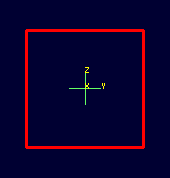
NIRT within MGED.Select the MGED view window and press "3" to view the path of
the ray:
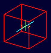
NIRT ray.Because the ray encountered only a single region, the only visible path drawn is the intersection path of the ray and the region (the light blue line). The region intersection was backed out to the first intersection with that region, despite the origination point of the ray being at the center of the sphere.
|
When a miss is reported by |
3.2. Backing Out with NIRT in MGED
Because NIRT's interactive mode cannot be used while in
MGED, the b flag must be provided to the invocation of the
nirt MGED command to back out the origination point while
using NIRT within MGED. For comparison purposes, it is
more instructive to examine left_and_right_cubes.r than
center_cube.r. To generate a "no backout" control view, the display
is cleared, left_and_right_cubes.r is drawn, the view direction is
set, NIRT (no b flag) is run, and the view is switched to
view the ray path:
mged> B left_and_right_cubes.r
mged> ae 0 0
mged> nirt

Firing from view center...
Origin (x y z) = (0.00 0.00 0.00)  (h v d) = (0.00 0.00 0.00)
Direction (x y z) = (-1.0000 -0.0000 0.0000)  (az el) = (0.00 -0.00)
    Region Name               Entry (x y z)              LOS  Obliq_in
region1.r            ( -300.000     0.000     0.000)   100.00    0.000

mged> ae 90 0
mged>
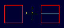
NIRT ray intersecting left_and_right_cubes.r with ray origin at the global origin.The ray did indeed intersect a solid area as indicated in the report, but only in one of the two cubes making up the region. Repeating the steps using the b flag to back the origination point out produces somewhat different results:
mged> ae 0 0
mged> nirt -b

Firing from view center...
Origin (x y z) = (6.63 0.00 0.00)  (h v d) = (0.00 0.00 0.00)
Direction (x y z) = (-1.0000 -0.0000 0.0000)  (az el) = (0.00 -0.00)
    Region Name               Entry (x y z)              LOS  Obliq_in
left_and_right_cubes.r (    3.000     0.000     0.000)     2.00    0.000
left_and_right_cubes.r (   -1.000     0.000     0.000)     2.00    0.000

mged> ae 90 0
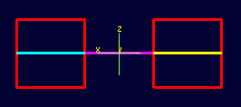
NIRT ray intersecting left_and_right_cubes.r with ray origin backed out of the region.Notice that the ray path is now drawn over a much larger area, and
multiple colors are used. The colors have significance; the purple
segment in the NIRT ray path corresponds to the empty area or
"gap" between the two solid areas.
3.3. Ray Segment Coloring with NIRT and MGED
NIRT uses colors to visually represent the information seen in
text form in its report. The conventions are:
| Property | Color |
|---|---|
Solid |
Alternates between Blue and Yellow |
Gap |
Purple |
Overlap |
White |
To illustrate these outputs, a series of cube configurations will be
examined. First, all three are drawn at once, the viewing direction
is set to the -x direction, nirt -b is run, and the view is changed
to see the results:
mged> B left_cube.r center_cube.r right_cube.r
mged> ae 0 0
mged> nirt -b

Firing from view center...
Origin (x y z) = (6.63 0.00 0.00)  (h v d) = (0.00 0.00 0.00)
Direction (x y z) = (-1.0000 -0.0000 0.0000)  (az el) = (0.00 -0.00)
    Region Name               Entry (x y z)              LOS  Obliq_in
right_cube.r         (    3.000     0.000     0.000)     2.00    0.000
center_cube.r        (    1.000     0.000     0.000)     2.00    0.000
left_cube.r          (   -1.000     0.000     0.000)     2.00    0.000

mged> ae 90 0
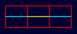
NIRT ray passing through all three cubes.There are three regions present, according to the text report. The first region encountered is that associated with right_cube.r, and the portion of the ray intersection in that region is light blue. The second region, center_cube.r, has its intersection with the yellow ray. Note the color of the intersection in left_cube.r is the same as that shown for right_cube.r. It is important to realize that the same intersection color in two different areas does NOT imply that they are the same region, material, etc. Nor do different colors guarantee that noncontiguous geometric areas are in different regions. The color swap is simply an aid when viewing two different contiguous solid regions that would otherwise be indistinguishable visually. For example, if all three cubes were unioned into a single region, the wireframe would look identical but the region report would be very different. In that case, there would be only one region, and only one line color would be needed. To illustrate:
mged> B all_cubes.r
mged> ae 0 0
mged> nirt -b

Firing from view center...
Origin (x y z) = (6.63 0.00 0.00)  (h v d) = (0.00 0.00 0.00)
Direction (x y z) = (-1.0000 -0.0000 0.0000)  (az el) = (0.00 -0.00)
    Region Name               Entry (x y z)              LOS  Obliq_in
all_cubes.r          (    3.000     0.000     0.000)     6.00    0.000

mged> ae 90 0
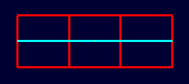
NIRT ray passing through the region on the same path as that used for the individual arb8 cubes.Without the color-changing mechanism, the two previous situations would have been visually identical despite having very different properties.
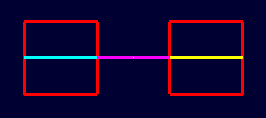
The other two situations that result in a color change are gaps and
overlaps. A gap in NIRT is any area along the ray path after
a solid portion of a region is encountered and before the last solid
portion of a region is encountered that does not intersect a region.
As an illustration, casting the same ray through just left_cube.r
and right_cube.r results in a gap where center_cube.r was in the
first example in this section:
mged> B left_cube.r right_cube.r
mged> ae 0 0
mged> nirt -b

Firing from view center...
Origin (x y z) = (6.63 0.00 0.00)  (h v d) = (0.00 0.00 0.00)
Direction (x y z) = (-1.0000 -0.0000 0.0000)  (az el) = (0.00 -0.00)
    Region Name               Entry (x y z)              LOS  Obliq_in
right_cube.r         (    3.000     0.000     0.000)     2.00    0.000
left_cube.r          (   -1.000     0.000     0.000)     2.00    0.000

mged> ae 90 0
To illustrate overlaps, both center_cube.r and all_cubes.r are drawn at the same time:
mged> B all_cubes.r center_cube.r
mged> ae 0 0
mged> nirt -b

Firing from view center...
Origin (x y z) = (6.63 0.00 0.00)  (h v d) = (0.00 0.00 0.00)
Direction (x y z) = (-1.0000 -0.0000 0.0000)  (az el) = (0.00 -0.00)
    Region Name               Entry (x y z)              LOS  Obliq_in
all_cubes.r          (    3.000     0.000     0.000)     6.00    0.000
OVERLAP: 'center_cube.r' and 'all_cubes.r' xyz_in=(1 0 0) los=2

mged> ae 90 0
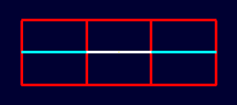
NIRT ray.3.4. Mouse-Based NIRT Usage
In addition to providing a nirt command on the MGED command
line, there is a mouse-based trigger that can be used. In the MGED
menu, selecting will change
the behavior of the mouse. Selecting the view window, placing the
mouse at some point over the model, and preforming a click will cast a
ray in the view direction, centered at the point under the mouse
pointer rather than the view center.
For this example, bring up left_cube.r, center_cube.r, and right_cube.r:
mged> B left_cube.r center_cube.r right_cube.r
mged>
To aid with aiming, the grid overlay is enabled from the menu: . Grid spacing is adjusted with :
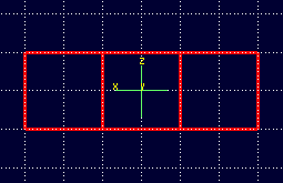
MGED wireframe.With the mouse behavior set to Query Ray, the following results are from casting rays at (approximately) the (-2 mm, 0 mm), (0 mm, 0 mm), and (2 mm, 0 mm) grid points:
Firing from (-1.992832, -4.000000, -0.028674)...
Origin (x y z) = (-1.99 -10.63 -0.03)  (h v d) = (-1.99 -0.03 4.00)
Direction (x y z) = (-0.0000 1.0000 0.0000)  (az el) = (-90.00 -0.00)
    Region Name               Entry (x y z)              LOS  Obliq_in
left_cube.r          (   -1.993    -1.000    -0.029)     2.00    0.000

Firing from (0.014337, -4.000000, -0.000000)...
Origin (x y z) = (0.01 -10.63 -0.00)  (h v d) = (0.01 0.00 4.00)
Direction (x y z) = (-0.0000 1.0000 0.0000)  (az el) = (-90.00 -0.00)
    Region Name               Entry (x y z)              LOS  Obliq_in
center_cube.r        (    0.014    -1.000     0.000)     2.00    0.000

Firing from (2.021505, -4.000000, -0.028674)...
Origin (x y z) = (2.02 -10.63 -0.03)  (h v d) = (2.02 -0.03 4.00)
Direction (x y z) = (-0.0000 1.0000 0.0000)  (az el) = (-90.00 -0.00)
    Region Name               Entry (x y z)              LOS  Obliq_in
right_cube.r         (    2.022    -1.000    -0.029)     2.00    0.000
Notice the entry points are off from the target values by small but significant amounts. A more precise way to do this analysis is to use the "snap to grid" feature. This feature is enabled by selecting . Repeating the above ray casts:
Firing from (-2.000000, -4.000000, -0.000000)...
Origin (x y z) = (-2.00 -10.63 -0.00)  (h v d) = (-2.00 0.00 4.00)
Direction (x y z) = (-0.0000 1.0000 0.0000)  (az el) = (-90.00 -0.00)
    Region Name               Entry (x y z)              LOS  Obliq_in
left_cube.r          (   -2.000    -1.000     0.000)     2.00    0.000

Firing from (0.000000, -4.000000, -0.000000)...
Origin (x y z) = (0.00 -10.63 -0.00)  (h v d) = (-0.00 0.00 4.00)
Direction (x y z) = (-0.0000 1.0000 0.0000)  (az el) = (-90.00 -0.00)
    Region Name               Entry (x y z)              LOS  Obliq_in
center_cube.r        (    0.000    -1.000     0.000)     2.00    0.000

Firing from (2.000000, -4.000000, -0.000000)...
Origin (x y z) = (2.00 -10.63 -0.00)  (h v d) = (2.00 0.00 4.00)
Direction (x y z) = (-0.0000 1.0000 0.0000)  (az el) = (-90.00 -0.00)
    Region Name               Entry (x y z)              LOS  Obliq_in
right_cube.r         (    2.000    -1.000     0.000)     2.00    0.000
These values are exact thanks to the corrections provided by the snap to grid mode.
3.5. Configuring NIRT with the Query Ray Control Panel
When using NIRT within MGED, some of its settings can be
changed through a graphical dialog found in the menu: MGED's
. This section will describe the
basic options. More advanced settings will be covered later.
3.5.1. Enabling and Disabling Mouse-Based nirt Ray Casting
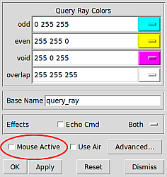
Earlier, mouse-based NIRT ray casting was enabled via a menu
option. The Query Ray Control Panel offers a more convenient option
for toggling the same behavior via the Mouse Active check box in the
lower left corner of the dialog box. Selecting this check box and
clicking Apply will activate the mouse as a trigger for a ray cast.
Clearing the Mouse Active check box and clicking Apply will
restore the default behavior.
MGED's Query Ray Control Panel with the Mouse Active check box circled.3.5.2. Customizing NIRT Coloring in MGED
Although the default colors normally work well, it is possible to adjust the colors used for regions, overlaps, and gaps:
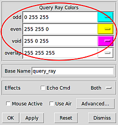
MGED's Query Ray Control Panel with the Query Ray Colors circled.The odd and even colors correspond to solid areas of regions, void is a gap between regions, and overlap is the color for overlapping regions. Select a color by typing in an RGB color designation directly or using the drop-down menu visible on the right end of each color entry:
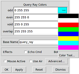
MGED's Query Ray Control Panel with an example color list selected.If the default color listings are insufficient, the Color Tool can be used for more fine-tuned selection:
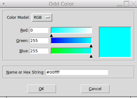
MGED's Color Tool3.5.3. Customizing the Pseudo-Primitive Base Name
MGED and NIRT use "pseudo" primitives to describe the
actual graphical lines. They will not behave like "normal"
primitives, but they do need a name. By default, these names are the
string "query_ray" and the color used for the string. For example,
the pseudo-primitive list after running NIRT on the cube
example with a gap is given below:

NIRT ray using multiple colors.mged> who p query_rayffff00 query_rayffff query_rayff00ff
This naming convention is used almost completely as an internal
mechanism by MGED and NIRT. For example, an l command
on query_rayffff does not work:
mged> l query_rayffff
rt_db_get_internal(query_rayffff) failure
However, it is possible to use these names to erase the NIRT
line segments from the drawing. For example, to remove the purple
line segments from the wireframe, the command:
mged> erase query_rayff00ff
will remove only the purple line segment and leave the others:
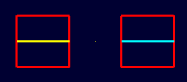
NIRT ray after erasing query_rayff00ff.The Query Ray Control Panel also offers a way to customize the base
name used for these pseudo-primitives. Changing the Base Name from
query_ray to line_segment and rerunning NIRT results in
pseudo-primitives named:
mged> who p
     line_segmentffff00 line_segmentffff line_segmentff00ff
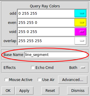
MGED's Query Ray Control Panel showing a new Base Name.3.5.4. Echoing the Internal nirt Command
The Echo Cmd check box in the Effects row allows the user to
enable/disable the printing of the internal nirt command being run
by MGED.
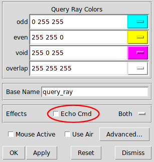
MGED's Query Ray Control Panel with the Echo Cmd check box circled.For example, with Echo Cmd selected, casting a ray into the last example in the previous section results in:
nirt -e fmt r ""; fmt h ""; fmt p ""; fmt m ""; fmt o ""; fmt f ""; fmt g "" -e fmt p
 "%e %e %e %e\n" x_in y_in z_in los -e xyz 4.000000 0.022222 0.011111;dir -1.000000
-0.000000 0.000000; s -e fmt r "\n" ; fmt p ""; fmt o "%e %e %e %e\n" ov_x_in ov_y_in
ov_z_in ov_los -e xyz 4.000000 0.022222 0.011111;dir -1.000000 -0.000000 0.000000; s
-e  fmt r "\nOrigin (x y z) = (%.2f %.2f %.2f)  (h v d) = (%.2f %.2f %.2f)\nDirection
(x y z) = (%.4f %.4f %.4f)  (az el) = (%.2f %.2f)\n"  x_orig y_orig z_orig h v d_orig
x_dir y_dir z_dir a e -e fmt h "    Region Name               Entry (x y z)
    LOS  Obliq_in\n"; fmt p "%-20s (%9.3f %9.3f %9.3f) %8.2f %8.3f\n" reg_name x_in
y_in z_in los obliq_in; fmt f ""; fmt m "You missed the target\n"; fmt o "OVERLAP:
'%s' and '%s' xyz_in=(%g %g %g) los=%g\n" ov_reg1_name ov_reg2_name ov_x_in ov_y_in
ov_z_in ov_los; fmt g "" -e xyz 4.000000 0.022222 0.011111;dir -1.000000 -0.000000
0.000000; s -b nirt_example.g right_cube.r center_cube.r left_cube.r

Firing from (4.000000, 0.022222, 0.011111)...
Origin (x y z) = (10.63 0.02 0.01)  (h v d) = (0.02 0.01 4.00)
Direction (x y z) = (-1.0000 -0.0000 0.0000)  (az el) = (0.00 -0.00)
    Region Name               Entry (x y z)              LOS  Obliq_in
right_cube.r         (    3.000     0.022     0.011)     2.00    0.000
center_cube.r        (    1.000     0.022     0.011)     2.00    0.000
left_cube.r          (   -1.000     0.022     0.011)     2.00    0.000
This feature is primarily useful for debugging or scripting outside of
MGED.
3.5.5. Selecting Graphical and Textual Output
By default, NIRT in MGED outputs both graphical and
text-based output. This is reflected in the drop-down menu on the
right side of the Effects row in the Query Ray Control Panel, which
is set to Both. The other options in the drop-down menu allow the
user to specify only Graphics (no text report is printed) or only
Text (no ray path is drawn in the wireframe.)
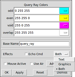
MGED's Query Ray Control Panel with the Effects drop-down menu shown.4. Reporting Options
Up until this point, only the default output configuration of
NIRT has been used. Much of the power of NIRT comes
from taking that output and changing the format and information to
supply precisely what is needed for any given purpose.
4.1. How to Change the Reporting Format
The f option allows NIRT to load customized formatting files
that change its reporting style. In addition to the default style
used thus far in this report, NIRT has several built-in options
for convenient formatting. Running nirt -L prints out a list of
available built-in formats, with a description of each:
user@machine ~ $ nirt -L
csv-gap   - Comma Separated Value Output Formatting with Gap Reporting
entryexit - Variation on Standard format that prints Entry and Exit points rather than LOS.
csv       - Comma Separated Value Output Formatting
gap2      - Reporting with Gap input point, output point and LOS
gap1      - Reporting with Gap Input Point and LOS
default   - Standard NIRT Reporting Format
To use a particular format, the name on the left (csv, gap1, etc.) is supplied as an argument to the f flag.
For example, cases where data needs to be imported into a spreadsheet can benefit from using comma-separated-variable (csv) output formatting. The individual cube regions are loaded and a ray cast:
user@machine ~ $ nirt -b -f csv nirt_example.g left_cube.r center_cube.r right_cube.r
BRL-CAD Release 7.13.0  Natalie's Interactive Ray Tracer
    Tue, 26 Aug 2008 23:21:32 -0400, Compilation 2
    user@localhost:/usr/brlcad
Database file:  'nirt_example.g'
Building the directory...
Get trees...
Prepping the geometry...
Objects 'left_cube.r' 'center_cube.r' 'right_cube.r' processed
Database title: 'Example BRL-CAD Database'
Database units: 'mm'
model_min = (-3, -1, -1)    model_max = (3, 1, 1)
nirt>  s
Ray:
x_orig,y_orig,z_orig,d_orig,h,v,x_dir,y_dir,z_dir,az,el
6.63324958,0.00000000,0.00000000,0.00000000,0.00000000,0.00000000,-1.00000000,0.000000...

Results:
reg_name,path_name,reg_id,x_in,y_in,z_in,d_in,x_out,y_out,z_out,d_out,los,scaled_los,o...
"right_cube.r","/right_cube.r",1002,3.000000,0.000000,0.000000,3.000000,1.000000,0.000...
"center_cube.r","/center_cube.r",1000,1.000000,0.000000,0.000000,1.000000,-1.000000,0...
"left_cube.r","/left_cube.r",1001,-1.000000,0.000000,0.000000,-1.000000,-3.000000,0.00...
The output of the shot command is then copied to a file (for example, test.csv) and imported into a spreadsheet:
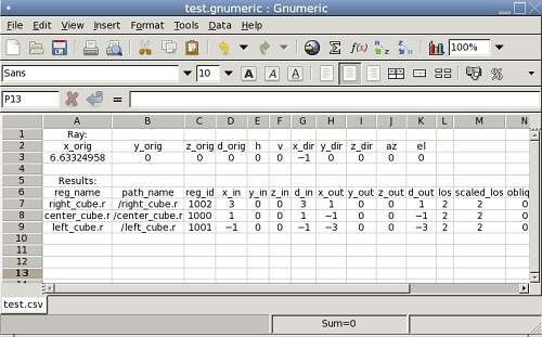
Since copying to a file is impractical in many cases, NIRT
provides an interactive command called dest which can specify an
output file. In the previous case, the test.csv file is created
easily:
nirt>  dest test.csv
nirt>  s
The file contents match the previous output:
Ray:
x_orig,y_orig,z_orig,d_orig,h,v,x_dir,y_dir,z_dir,az,el
6.63324958,0.00000000,0.00000000,0.00000000,0.00000000,0.00000000,-1.00000000,0.000000...

Results:
reg_name,path_name,reg_id,x_in,y_in,z_in,d_in,x_out,y_out,z_out,d_out,los,scaled_los,o...
"right_cube.r","/right_cube.r",1002,3.000000,0.000000,0.000000,3.000000,1.000000,0.000...
"center_cube.r","/center_cube.r",1000,1.000000,0.000000,0.000000,1.000000,-1.000000,0...
"left_cube.r","/left_cube.r",1001,-1.000000,0.000000,0.000000,-1.000000,-3.000000,0.00...
To restore output to the command line, use dest default to redirect
to standard output:
nirt> dest default
When dealing with spaces between models, it is sometimes advantageous
to report gaps in NIRT's output. MGED's
visualization routines show gaps between regions as purple lines, but
the default text report does not include information about gaps.
Sometimes it is desirable to get exact information on gaps,
particularly when they represent errors in a model. The gap1 and
gap2 formats will include information about gaps. Running
NIRT on the left_and_right_cubes.r object with backout
enabled provides an example:
user@machine ~ $ nirt -b -f gap2 nirt_example.g left_and_right_cubes.r
BRL-CAD Release 7.13.0  Natalie's Interactive Ray Tracer
    Tue, 26 Aug 2008 23:21:32 -0400, Compilation 2
    user@localhost:/usr/brlcad
Database file:  'nirt_example.g'
Building the directory...
Get trees...
Prepping the geometry...
Object 'left_and_right_cubes.r' processed
Database title: 'Example BRL-CAD Database'
Database units: 'mm'
model_min = (-3, -1, -1)    model_max = (3, 1, 1)
nirt>  s
Origin (x y z) = (6.63324958 0.00000000 0.00000000)  (h v d) = (0.0000 0.0000 0.0000)
Direction (x y z) = (-1.00000000 0.00000000 0.00000000)  (az el) = (0.00000000 0.00000000)
    Region Name               Entry (x y z)              LOS  Obliq_in Attrib
left_and_right_cubes.r (   3.0000    0.0000    0.0000)   2.0000   0.0000
GAP: xyz_in=(1 0 0) xyz_out=(-1 0 0) los=2
left_and_right_cubes.r (  -1.0000    0.0000    0.0000)   2.0000   0.0000
4.2. Handling Attribute Reporting
The default command line reporting format lists an Attrib column
where attributes may be printed, but does not print any as default
output. Including attributes in a NIRT report requires adding
attributes in question to the attributes table using the attr
command. For example, if the user wants the report to identify the
rgb color being used for each region:
user@machine ~ $ nirt -b nirt_example.g left_cube_color.r center_cube_color.r right_cube_color.r
nirt>  attr rgb
nirt>  attr -p
"rgb"
nirt>  s

Get trees...
Prepping the geometry...
Objects 'left_cube_color.r' 'center_cube_color.r' 'right_cube_color.r' processed
Origin (x y z) = (6.63324958 0.00000000 0.00000000)  (h v d) = (0.0000 0.0000 0.0000)
Direction (x y z) = (-1.00000000 0.00000000 0.00000000)  (az el) = (0.00000000 0.00000000)
    Region Name               Entry (x y z)              LOS  Obliq_in Attrib
right_cube_color.r   (   3.0000    0.0000    0.0000)   2.0000   0.0000 rgb=255/0/0
center_cube_color.r  (   1.0000    0.0000    0.0000)   2.0000   0.0000 rgb=0/255/0
left_cube_color.r    (  -1.0000    0.0000    0.0000)   2.0000   0.0000 rgb=0/0/255
Notice how the report now includes the rgb attribute for each region. The p flag prints the current list of attributes to include. In the previous case it’s simply the "rgb" attribute. An f option can be supplied to flush all entries and clear the table.
nirt>  attr -f
nirt>  attr -p
Multiple attributes can also be specified:
nirt>  attr rgb region
nirt>  attr -p
"rgb"
"region"
nirt>  s

Get trees...
Prepping the geometry...
Objects 'left_cube_color.r' 'center_cube_color.r' 'right_cube_color.r' processed
Origin (x y z) = (6.63324958 0.00000000 0.00000000)  (h v d) = (0.0000 0.0000 0.0000)
Direction (x y z) = (-1.00000000 0.00000000 0.00000000)  (az el) = (0.00000000 0.00000000)
    Region Name               Entry (x y z)              LOS  Obliq_in Attrib
right_cube_color.r   (   3.0000    0.0000    0.0000)   2.0000   0.0000 rgb=255/0/0 region=R
center_cube_color.r  (   1.0000    0.0000    0.0000)   2.0000   0.0000 rgb=0/255/0 region=R
left_cube_color.r    (  -1.0000    0.0000    0.0000)   2.0000   0.0000 rgb=0/0/255 region=R
If the user wishes to add yet another attribute, it could be appended
to the current list with another attr command.
To provide attributes to the list on startup, the A option will add its arguments to the list:
user@machine ~ $ nirt -b -A rgb nirt_example.g left_cube_color.r center_cube_color.r right_cube_color.r
BRL-CAD Release 7.13.0  Natalie's Interactive Ray Tracer
    Mon, 25 Aug 2008 15:14:03 -0400, Compilation 1
    user@localhost:/usr/brlcad
Database file:  'nirt_example.g'
Building the directory...
Get trees...
Prepping the geometry...
Objects 'left_cube_color.r' 'center_cube_color.r' 'right_cube_color.r' processed
Database title: 'Example BRL-CAD Database'
Database units: 'mm'
model_min = (-3, -1, -1)    model_max = (3, 1, 1)
nirt>  s
Origin (x y z) = (6.63324958 0.00000000 0.00000000)  (h v d) = (0.0000 0.0000 0.0000)
Direction (x y z) = (-1.00000000 0.00000000 0.00000000)  (az el) = (0.00000000 0.00000...
    Region Name               Entry (x y z)              LOS  Obliq_in Attrib
right_cube_color.r   (   3.0000    0.0000    0.0000)   2.0000   0.0000 rgb=255/0/0
center_cube_color.r  (   1.0000    0.0000    0.0000)   2.0000   0.0000 rgb=0/255/0
left_cube_color.r    (  -1.0000    0.0000    0.0000)   2.0000   0.0000 rgb=0/0/255
|
Reporting attributes when running |
4.3. Changing Units
By default NIRT's interactive command line mode reads and
writes all dimensions in millimeters, regardless of the units set in
the geometry file. This is configurable via the units command,
which will accept mm, cm, m, in, and ft as arguments or print the
current unit with no arguments. Using center_cube.r as an example:
nirt>  units
units = 'mm'
nirt>  s
Origin (x y z) = (3.46410162 0.00000000 0.00000000)  (h v d) = (0.0000 0.0000 0.0000)
Direction (x y z) = (-1.00000000 0.00000000 0.00000000)  (az el) = (0.00000000 0.00000000)
    Region Name               Entry (x y z)              LOS  Obliq_in Attrib
center_cube.r        (   1.0000    0.0000    0.0000)   2.0000   0.0000
nirt>  units m
nirt>  s
Origin (x y z) = (0.00346410 0.00000000 0.00000000)  (h v d) = (0.0000 0.0000 0.0000)
Direction (x y z) = (-1.00000000 0.00000000 0.00000000)  (az el) = (0.00000000 0.00000000)
    Region Name               Entry (x y z)              LOS  Obliq_in Attrib
center_cube.r        (   0.0010    0.0000    0.0000)   0.0020   0.0000
nirt>  units in
nirt>  s
Origin (x y z) = (0.13638195 0.00000000 0.00000000)  (h v d) = (0.0000 0.0000 0.0000)
Direction (x y z) = (-1.00000000 0.00000000 0.00000000)  (az el) = (0.00000000 0.00000000)
    Region Name               Entry (x y z)              LOS  Obliq_in Attrib
center_cube.r        (   0.0394    0.0000    0.0000)   0.0787   0.0000
nirt>  units ft
nirt>  s
Origin (x y z) = (0.01136516 0.00000000 0.00000000)  (h v d) = (0.0000 0.0000 0.0000)
Direction (x y z) = (-1.00000000 0.00000000 0.00000000)  (az el) = (0.00000000 0.00000000)
    Region Name               Entry (x y z)              LOS  Obliq_in Attrib
center_cube.r        (   0.0033    0.0000    0.0000)   0.0066   0.0000
When run from within MGED, NIRT uses the current units
set within the MGED environment.
5. Other Options
5.1. Silent and Verbose Modes
NIRT supports two behaviors associated with output verbosity.
The interactive command line environment uses the verbose mode by
default. Verbose mode prints out the headers containing information
about the BRL-CAD version number, database name, database title, etc.
and also provides the "nirt>" command prompt label. Silent mode,
used by default inside the MGED command window, does not print any
headers or prompt label.
When generating large numbers of results, it is sometimes desirable to
switch to silent mode on the command line. This is accomplished by
supplying the s option to nirt. Similarly, in the MGED
window, supplying the v option will produce the full text output of
NIRT's interactive mode in the MGED window.
5.2. Using Air Regions
Air regions have a special status in BRL-CAD, and by default
NIRT does not report them. If the user does wish to have air
regions reported, the u option is supplied with an argument of 1 to
activate air region reporting. This is illustrated with a
center_cube_air.r object:
user@machine $ nirt -s -b -u 0 -f gap2 nirt_example.g left_and_right_cubes.r center_cube_air.r
s
Origin (x y z) = (6.63324958 0.00000000 0.00000000)  (h v d) = (0.0000 0.0000 0.0000)
Direction (x y z) = (-1.00000000 0.00000000 0.00000000)  (az el) = (0.00000000 0.00000000)
    Region Name               Entry (x y z)              LOS  Obliq_in Attrib
left_and_right_cubes.r (   3.0000    0.0000    0.0000)   2.0000   0.0000
GAP: xyz_in=(1 0 0) xyz_out=(-1 0 0) los=2
left_and_right_cubes.r (  -1.0000    0.0000    0.0000)   2.0000   0.0000


user@machine $ nirt -s -b -u 1 -f gap2 nirt_example.g left_and_right_cubes.r center_cube_air.r
s
Origin (x y z) = (6.63324958 0.00000000 0.00000000)  (h v d) = (0.0000 0.0000 0.0000)
Direction (x y z) = (-1.00000000 0.00000000 0.00000000)  (az el) = (0.00000000 0.00000000)
    Region Name               Entry (x y z)              LOS  Obliq_in Attrib
left_and_right_cubes.r (   3.0000    0.0000    0.0000)   2.0000   0.0000
center_cube_air.r    (   1.0000    0.0000    0.0000)   2.0000   0.0000
left_and_right_cubes.r (  -1.0000    0.0000    0.0000)   2.0000   0.0000
In the first case, area in between the cubes of left_and_right_cubes.r is reported as a gap when gap reporting is enabled. In the second case, center_cube_air.r is treated as a region and a new region report line is generated instead of a gap report.
The Query Ray Control Panel also offers a way to select the Use Air option:
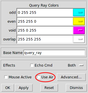
MGED's Query Ray Control Panel showing the Use Air check box.5.3. Reading an Orientation Matrix and Commands
This option is seldom used manually from the command line. Its
primary purpose is to allow MGED's saveview command to
generate scripts that allow commands run on MGED views to be
repeated on the command line. By default the saveview MGED
command generates scripts to run rt, so it is necessary to specify
nirt with saveview's e option; for example saveview -e nirt
tsv.script. Typically the saveview MGED command generates
scripts with a few other options included, but the important parts are
the orientation matrix and eyepoint:
#!/bin/sh
nirt -M  nirt_example.g 'right_cube.r' 'center_cube.r' 'left_cube.r'  <<EOF
orientation 2.480973490458727e-01 4.765905732660485e-01 7.480973490458729e-01 \
	    3.894348305183902e-01;
eye_pt 6.000000000000000e+00 4.201245229258262e+00 3.415539237722919e+00;
When the above script is run, a NIRT report is generated for a
ray cast in the same direction as that which would have been cast in
the original MGED view where the saveview command was run:
machine:~ user$ sh tsv.script
Origin (x y z) = (6.00000000 4.20124523 3.41553924)  (h v d) = (0.0000 0.0000 8.0819)
Direction (x y z) = (-0.74240388 -0.51983679 -0.42261826)  (az el) = (35.00000000 25.00000000)
    Region Name               Entry (x y z)              LOS  Obliq_in Attrib
right_cube.r         (   1.4281    1.0000    0.8130)   0.5767  58.6787
center_cube.r        (   1.0000    0.7002    0.5693)   2.6940  42.0634
left_cube.r          (  -1.0000   -0.7002   -0.5693)   0.5767  42.0634
Notice the az and el reported are 35 and 25, which correspond to
the settings for those values in MGED when saveview was run.
6. Scripting NIRT
As mentioned in the output formatting section, hand-copying
NIRT output can be an inconvenient way to store results,
particularly in cases where large numbers of rays will be cast. In
such cases, it is possible to automate NIRT usage with
scripting.
6.1. Command Line Scripts: The e Option
The most straightforward approach to supplying NIRT with a
series of commands is to do so in a string from the command line using
the e option. The format of such a string is nirt -e "command1;
command2; … commandn" model.g object. For example, to cast a ray
in the negative z direction and avoid interactive mode, the following
would work:
user@machine ~ $ nirt -b -s -e "dir 0 0 -1; s; q" nirt_example.g all_cubes.r
Origin (x y z) = (0.00000000 0.00000000 6.63324958)  (h v d) = (0.0000 0.0000 0.0000)
Direction (x y z) = (0.00000000 0.00000000 -1.00000000)  (az el) = (0.00000000 90.00000000)
    Region Name               Entry (x y z)              LOS  Obliq_in Attrib
all_cubes.r          (   0.0000    0.0000    1.0000)   2.0000   0.0000
It’s important to be aware that the order of e and f options matters. They are read in from left to right and each option is aware of the effects of the previous options. Using the gap format with the left_and_right_cubes.r object, both orders of the e and f options produce different results:
user@machine ~ $ nirt -b -s -f gap2 -e "s; q" nirt_example.g left_and_right_cubes.r
Origin (x y z) = (6.63324958 0.00000000 0.00000000)  (h v d) = (0.0000 0.0000 0.0000)
Direction (x y z) = (-1.00000000 0.00000000 0.00000000)  (az el) = (0.00000000 0.00000000)
    Region Name               Entry (x y z)              LOS  Obliq_in Attrib
left_and_right_cubes.r (   3.0000    0.0000    0.0000)   2.0000   0.0000
GAP: xyz_in=(1 0 0) xyz_out=(-1 0 0) los=2
left_and_right_cubes.r (  -1.0000    0.0000    0.0000)   2.0000   0.0000

user@machine ~ $ nirt -b -s -e "s; q" -f gap2 nirt_example.g left_and_right_cubes.r
Origin (x y z) = (6.63324958 0.00000000 0.00000000)  (h v d) = (0.0000 0.0000 0.0000)
Direction (x y z) = (-1.00000000 0.00000000 0.00000000)  (az el) = (0.00000000 0.00000000)
    Region Name               Entry (x y z)              LOS  Obliq_in Attrib
left_and_right_cubes.r (   3.0000    0.0000    0.0000)   2.0000   0.0000
left_and_right_cubes.r (  -1.0000    0.0000    0.0000)   2.0000   0.0000
In the second case, the arguments to e were executed before the formatting change was reached. A final illustration of this behavior uses multiple instances of the e and f options:
user@machine ~ $ nirt -b -s -e "s" -f gap2 -e "s; q" nirt_example.g left_and_right_cubes.r
Origin (x y z) = (6.63324958 0.00000000 0.00000000)  (h v d) = (0.0000 0.0000 0.0000)
Direction (x y z) = (-1.00000000 0.00000000 0.00000000)  (az el) = (0.00000000 0.00000000)
    Region Name               Entry (x y z)              LOS  Obliq_in Attrib
left_and_right_cubes.r (   3.0000    0.0000    0.0000)   2.0000   0.0000
left_and_right_cubes.r (  -1.0000    0.0000    0.0000)   2.0000   0.0000
Origin (x y z) = (6.63324958 0.00000000 0.00000000)  (h v d) = (0.0000 0.0000 0.0000)
Direction (x y z) = (-1.00000000 0.00000000 0.00000000)  (az el) = (0.00000000 0.00000000)
    Region Name               Entry (x y z)              LOS  Obliq_in Attrib
left_and_right_cubes.r (   3.0000    0.0000    0.0000)   2.0000   0.0000
GAP: xyz_in=(1 0 0) xyz_out=(-1 0 0) los=2
left_and_right_cubes.r (  -1.0000    0.0000    0.0000)   2.0000   0.0000
Notice how the commands in the first e option are run without the gap formatting, but the command in the second is run with gap formatting.
6.2. Script Files: Other Uses of the f Option
Earlier, the f option was used to change the output formatting of
NIRT. This is only one instance of using scripted commands in
files to control NIRT. The same principles apply for any
command normally available during an interactive NIRT session.
Instead of hand-copying the output to a file as was done in the previous example using tire.g, a more ambitious goal is to output the results of several different ray casts to a single file without manual copying. A script file is defined thus:
# testscript: A Scripted NIRT Example
backout 1
dir -1 0 0
s
dir 1 0 0
s
q
Because the intent is to have only the output in the file, the s
option is supplied to the nirt command. The output is redirected to
a file called output.txt [4]
nirt -s -f testscript nirt_example.g left_and_right_cubes.r > output.txt
The contents of that file are the text reports of the two rays cast into the model:
Origin (x y z) = (6.63324958 0.00000000 0.00000000)  (h v d) = (0.0000 0.0000 0.0000)
Direction (x y z) = (-1.00000000 0.00000000 0.00000000)  (az el) = (-0.00000000 -0.00000000)
    Region Name               Entry (x y z)              LOS  Obliq_in Attrib
left_and_right_cubes.r (   3.0000    0.0000    0.0000)   2.0000   0.0000
left_and_right_cubes.r (  -1.0000    0.0000    0.0000)   2.0000   0.0000
Origin (x y z) = (-6.63324958 0.00000000 0.00000000)  (h v d) = (0.0000 0.0000 0.0000)
Direction (x y z) = (1.00000000 0.00000000 0.00000000)  (az el) = (-180.00000000 -0.00000000)
    Region Name               Entry (x y z)              LOS  Obliq_in Attrib
left_and_right_cubes.r (  -3.0000    0.0000    0.0000)   2.0000   0.0000
left_and_right_cubes.r (   1.0000    0.0000    0.0000)   2.0000   0.0000
This is useful, but more interesting would be the above output in csv
format. Fortunately, the f option can be used multiple times in a
single nirt run:
nirt -s -f csv -f testscript nirt_example.g left_and_right_cubes.r > output.csv
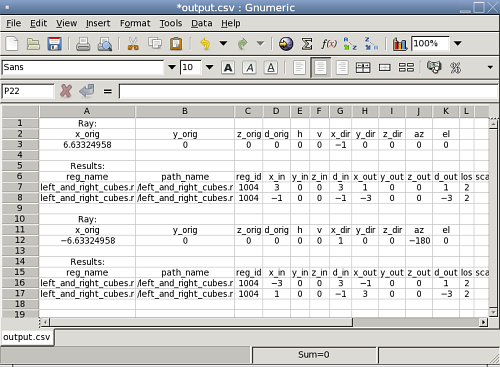
As mentioned in the earlier section when combinations of e and f options were used, using multiple instances of the f option in this fashion requires paying attention to the left-to-right order. The csv script in the above case is executed before testscript. The result is the csv equivalent of the preceding file:
Ray:
x_orig,y_orig,z_orig,d_orig,h,v,x_dir,y_dir,z_dir,az,el
6.63324958,0.00000000,0.00000000,0.00000000,0.00000000,0.00000000,-1.00000000,0.00000...

Results:
reg_name,path_name,reg_id,x_in,y_in,z_in,d_in,x_out,y_out,z_out,d_out,los,scaled_los,...
"left_and_right_cubes.r","/left_and_right_cubes.r",1004,3.000000,0.000000,0.000000,3....
"left_and_right_cubes.r","/left_and_right_cubes.r",1004,-1.000000,0.000000,0.000000,-...

Ray:
x_orig,y_orig,z_orig,d_orig,h,v,x_dir,y_dir,z_dir,az,el
-6.63324958,0.00000000,0.00000000,0.00000000,0.00000000,0.00000000,1.00000000,0.00000...

Results:
reg_name,path_name,reg_id,x_in,y_in,z_in,d_in,x_out,y_out,z_out,d_out,los,scaled_los,...
"left_and_right_cubes.r","/left_and_right_cubes.r",1004,-3.000000,0.000000,0.000000,3...
"left_and_right_cubes.r","/left_and_right_cubes.r",1004,1.000000,0.000000,0.000000,-1...
As before, this format is trivially imported into a spreadsheet:
6.3. Defining a Custom Reporting Format
A final example of the use of the scripting mechanism is constructing
a custom-tailored report format and specifying it using the f
option. In the case of a custom file stored in a user directory, the
full file name needs to be supplied just like any other script, e.g.,
nirt -f my_report_format.nrt model.g item.
Generally, it is simplest to use one of the predefined files as a starting point. For example, if the user prefers to have commas between xyz coordinates, but otherwise wishes to use the default format, the default.nrt file from the installed BRL-CAD system is copied to the local directory and renamed default-commas.nrt:
machine:~ user$ cp /usr/brlcad/share/brlcad/7.12.5/nirt/default.nrt default-commas.nrt

machine:~ user$ more default-commas.nrt
# default.nrt
# Description: default   - Standard NIRT Reporting Format
fmt r "Origin (x y z) = (%.8f %.8f %.8f)  (h v d) = (%.4f %.4f %.4f)\nDirection (x y z)...
fmt h "    Region Name               Entry (x y z)              LOS  Obliq_in Attrib\n"
fmt p "%-20s (%9.4f %9.4f %9.4f) %8.4f %8.4f %s\n" reg_name x_in y_in z_in los obliq_in...
fmt m "You missed the target\n"
fmt o "OVERLAP: '%s' and '%s' xyz_in=(%g %g %g) los=%g\n" ov_reg1_name ov_reg2_name ov_...
Next, the file is edited to replace all of the spaces in the point strings with commas:
machine:~ user$ more default-commas.nrt
fmt r "Origin (x,y,z) = (%.8f,%.8f,%.8f)  (h,v,d) = (%.4f,%.4f,%.4f)\nDirection (x,y,z...
fmt h "    Region Name               Entry (x,y,z)              LOS  Obliq_in Attrib\n"
fmt p "%-20s (%9.4f,%9.4f,%9.4f) %8.4f %8.4f %s\n" reg_name x_in y_in z_in los obliq_i...
fmt f ""
fmt m "You missed the target\n"
fmt o "OVERLAP: '%s' and '%s' xyz_in=(%g,%g,%g) los=%g\n" ov_reg1_name ov_reg2_name ov...
fmt g ""
Running the center_cube.r object:
machine:~ user$ nirt -s -b -f default-commas.nrt nirt_example.g center_cube.r
s
Origin (x,y,z) = (3.46410162,0.00000000,0.00000000)  (h,v,d) = (0.0000,0.0000,0.0000)
Direction (x,y,z) = (-1.00000000,0.00000000,0.00000000)  (az,el) = (0.00000000,0.00000000)
    Region Name               Entry (x,y,z)              LOS  Obliq_in Attrib
center_cube.r        (   1.0000,   0.0000,   0.0000)   2.0000   0.0000
Notice the commas now present between points. This file can be saved
and reused on any NIRT task.
|
If a user wishes to save the current session configuration of an
interactive command line |
6.4. Customizing Report Output in MGED
The Query Ray Control Panel discussed earlier also provides access to
the reporting logic used by MGED when calling NIRT, but
it does not provide any graphical aid when it comes to laying out the
formatting. All layout logic must be defined with the same syntax
already seen for the script files. Customizations of this logic in
MGED are done using the Advanced option in the lower right
corner of the Query Ray Control Panel, which brings up the following
window:
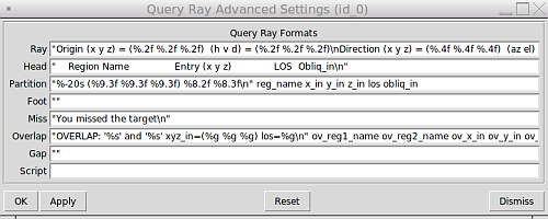
MGED's Query Ray Control Panel Advanced Settings dialog box.Note also the last line of this dialog box, which provides a place for
script commands to be executed before the internal s command is run.
It functions just like the -e option on the normal command line,
including the syntax of separating all commands except the last one
with semicolons. This is useful for setup not possible in normal
command line operation, as illustrated in the next section.
6.5. Reporting Attributes in MGED: Advanced Formatting and Scripting
As mentioned earlier, reporting attributes with NIRT inside of
MGED is more involved than the strictly command line interface
allows. In default NIRT reporting inside MGED, the
attributes column is not even listed. Attributes can be reported
with NIRT in MGED, but it requires custom formatting and
scripting.
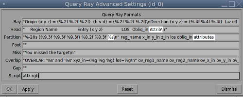
The first step is to open the Query Ray Advanced Settings dialog box
shown in the previous section. Examining the default NIRT
formatting file used on the command line reveals that the partition
formatting string needs a %s variable added and the attributes
variable in position to be supplied to the %s. Also the Attrib
column header is added to Head.
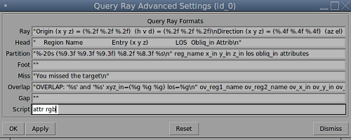
The second step is to use the Script line in this dialog box to add
rgb to the attributes list. Because the script line is run before
MGED sends the s command, the attributes list will be updated
by the time the ray is cast and the subsequent report is generated.
Unless graphical visualization is needed, it is probably simpler to
work from the NIRT interactive command line in cases where a
lot of adjustment of attribute reporting is needed. If MGED is
needed, however, this technique will allow custom reports inside of
MGED that include attributes.
6.6. Available Information for Inclusion in Reports
There are many cases where the user may want to change what
NIRT is reporting, instead of or in addition to the
formatting of the reports. NIRT internally defines values
that it supports as output options, most of which are not reported in
the default format for the sake of brevity and clarity. It also
defines "events" corresponding to various model geometric states
encountered by the ray, which are used to trigger print events:
| Event | Description |
|---|---|
r |
Ray. A ray is cast. The formatting associated with r will print regardless of whether a region is encountered. |
h |
Header. First output after a ray hits anything. Formatting at h is output once per ray. |
p |
Partition. Output for each region encountered by the ray. Typically this will be where most of the information about a model is reported. |
f |
Footnote. Last output statement after a ray hits anything; a "footnote" line after the ray has completed its evaluations; once per ray. |
g |
Gap. Output written once for each gap the ray may encounter. |
m |
Miss. If triggered, prints a message that nothing was hit; maximum once per ray. |
o |
Overlap. Output written once for each overlap along the ray. |
The available variables pertain to the ray, partitions, overlaps, and gaps. Other event options typically use only labeling strings. The variables are listed in Appendix A and can be used to change reported information. The csv output format is one example of such use.
7. Summary
-
NIRTis the standard, interactive ray trace query tool used for obtaining precise, detailed information about specific areas of a model via individual ray queries. -
NIRToffers a wide variety of formatting options for various analysis needs as well as support for custom formats. -
Running
NIRTwithinMGEDoffers additional graphical feedback not available when run outside ofMGED. -
NIRTprovides both command-line and file-based scripting to allow for powerful, automated, custom analyses.
Appendix A: Report Format Variable Listings
| Ray Variables | |
|---|---|
x_orig |
x coordinate of ray origination point. |
y_orig |
y coordinate of ray origination point. |
z_orig |
z coordinate of ray origination point. |
d_orig |
d coordinate of ray origination point. |
h |
h coordinate for the entire ray. |
v |
v coordinate for the entire ray. |
x_dir |
x component of direction vector. |
y_dir |
y component of direction vector. |
z_dir |
z component of direction vector. |
a |
azimuth of view (i.e., of ray direction). |
e |
elevation of view (i.e., of ray direction). |
| Partition Variables | |
|---|---|
attributes |
A string variable consisting of the names and values of the
attributes requested by the |
x_in |
x coordinate of entry into current region. |
y_in |
y coordinate of entry into current region. |
z_in |
z coordinate of entry into current region. |
d_in |
d coordinate of entry into current region. |
x_out |
x coordinate of exit from current region. |
y_out |
y coordinate of exit from current region. |
z_out |
z coordinate of exit from current region. |
d_out |
d coordinate of exit from current region. |
los |
line-of-sight distance through current region. |
scaled_los |
scaled line of sight: product of line-of-sight distance through current region and region solidity [5] (sometimes called ``percent LOS''). |
path_name |
full path name of current region. |
reg_name |
name of current region |
reg_id |
region ID of current region. |
claimant_count |
number of regions claiming this partition (that is, participating in a retained overlap). |
claimant_list |
space-separated list of names of regions claiming this partition (that is, participating in a retained overlap). |
claimant_listn |
Same as claimant_list, except that it is newline-, rather than space-separated. |
obliq_in |
entry obliquity for current region. |
obliq_out |
exit obliquity for current region. |
nm_x_in |
x component of entry normal vector |
nm_y_in |
y component of entry normal vector |
nm_z_in |
z component of entry normal vector |
nm_h_in |
h component of entry normal vector |
nm_v_in |
v component of entry normal vector |
nm_d_in |
d component of entry normal vector |
nm_x_out |
x component of exit normal vector |
nm_y_out |
y component of exit normal vector |
nm_z_out |
z component of exit normal vector |
nm_h_out |
h component of exit normal vector |
nm_v_out |
v component of exit normal vector |
nm_d_out |
d component of exit normal vector |
surf_num_in |
entry-surface ID of entry solid. |
surf_num_out |
exit-surface ID of exit solid. |
| Overlap Variables | |
|---|---|
ov_reg1_name |
name of one of the overlapping regions. |
ov_reg2_name |
name of the other overlapping region. |
ov_reg1_id |
region ID of one of the overlapping regions. |
ov_reg2_id |
region ID of the other overlapping region. |
ov_sol_in |
name of one of the overlapping solids. |
ov_sol_out |
name of the other overlapping solid. |
ov_los |
line-of-sight distance through the overlap. |
ov_x_in |
x coordinate of entry into overlap. |
ov_y_in |
y coordinate of entry into overlap. |
ov_z_in |
z coordinate of entry into overlap. |
ov_d_in |
d coordinate of entry into overlap. |
ov_x_out |
x coordinate of exit from overlap. |
ov_y_out |
y coordinate of exit from overlap. |
ov_z_out |
z coordinate of exit from overlap. |
ov_d_out |
d coordinate of exit from overlap. |
| Gap Variables | |
|---|---|
x_gap_in |
x coordinate of entry into gap. |
y_gap_in |
y coordinate of entry into gap. |
z_gap_in |
z coordinate of entry into gap. |
gap_los |
line-of-sight distance through gap. |
Appendix B: Debugging Options
In cases where problems are being encountered, it is possible to use debugging options to print additional information from the supporting BRL-CAD libraries.
librt Debugging Information
In cases where detailed behavior of the core raytracing routines is of interest, it is possible to use the x (lower case "x") option to print additional diagnostic messages. [6] See the librt header files for more detail about the very extensive debugging options provided.
machine:~ user$ nirt -s -b -x 0x002 -e "s; q" nirt_example.g center_cube.r

  **********shootray cpu=0  0,0 lvl=0 a_onehit=0 (NIRT ray)
  Pnt (3.4641016151377543864, 0, 0)
  Dir (-1, 0, 0)
    ------Partition list passed to a_hit() routine
    00604d50: PT center_cube.s (ARB8#0) center_cube.s (ARB8#0) (2.4641,4.4641)
      InHIT dist=2.4641 (surf 5)
     OutHIT dist=4.4641 (surf 4)
      Primitives: center_cube.s,
      Untrimmed Segments spanning this interval:
	0680d600: SEG center_cube.s (2.4641,4.4641) st_bit=0 xray#=0
      Region: /center_cube.r
  ------
Origin (x y z) = (3.46410162 0.00000000 0.00000000)  (h v d) = (0.0000 0.0000 0.0000)
Direction (x y z) = (-1.00000000 0.00000000 0.00000000)  (az el) = (0.00000000 0.00000000)
    Region Name               Entry (x y z)              LOS  Obliq_in Attrib
center_cube.r        (   1.0000    0.0000    0.0000)   2.0000   0.0000
----------shootray cpu=0  0,0 lvl=0 (NIRT ray) HIT ret=1
NIRT Debugging Information
NIRT itself also provides debugging information. It is
accessed using the X option. [7] NIRT provides five
different debug flags, as seen in nirt.h:
/** FLAG VALUES FOR nirt_debug */
#define DEBUG_INTERACT  0x001
#define DEBUG_SCRIPTS   0x002
#define DEBUG_MAT       0x004
#define DEBUG_BACKOUT   0x008
#define DEBUG_HITS      0x010
0x001 and 0x002 pertain to interaction and scripts, respectively:
machine:~ user$ nirt -s -b -X 0x001 -e "s; q" nirt_example.g center_cube.r
interact(READING_STRING, 603c10)...
sgetc((null)) '(null)' '(null)'... initializing
sgetc(s; q) '(null)' '(null)'... initializing
returning 's' (o163)
line_buffer[0] = 's' (o163)
sgetc(s; q) 's; q' '; q'... returning ';' (o73)
Line buffer contains 's'
Origin (x y z) = (3.46410162 0.00000000 0.00000000)  (h v d) = (0.0000 0.0000 0.0000)
Direction (x y z) = (-1.00000000 0.00000000 0.00000000)  (az el) = (0.00000000 0.00000000)
    Region Name               Entry (x y z)              LOS  Obliq_in Attrib
center_cube.r        (   1.0000    0.0000    0.0000)   2.0000   0.0000
sgetc(s; q) 's; q' ' q'... returning ' ' (o40)
Skipping ' '
sgetc(s; q) 's; q' 'q'... returning 'q' (o161)
line_buffer[0] = 'q' (o161)
sgetc(s; q) 's; q' ''... returning EOS
Line buffer contains 'q'


machine:~ user$ nirt -s -b -X 0x002 -e "s; q" nirt_example.g center_cube.r
interact(READING_STRING, 603c10)...
sgetc((null)) '(null)' '(null)'... initializing
sgetc(s; q) '(null)' '(null)'... initializing
returning 's' (o163)
line_buffer[0] = 's' (o163)
sgetc(s; q) 's; q' '; q'... returning ';' (o73)
Line buffer contains 's'
Origin (x y z) = (3.46410162 0.00000000 0.00000000)  (h v d) = (0.0000 0.0000 0.0000)
Direction (x y z) = (-1.00000000 0.00000000 0.00000000)  (az el) = (0.00000000 0.00000000)
    Region Name               Entry (x y z)              LOS  Obliq_in Attrib
center_cube.r        (   1.0000    0.0000    0.0000)   2.0000   0.0000
sgetc(s; q) 's; q' ' q'... returning ' ' (o40)
Skipping ' '
sgetc(s; q) 's; q' 'q'... returning 'q' (o161)
line_buffer[0] = 'q' (o161)
sgetc(s; q) 's; q' ''... returning EOS
Line buffer contains 'q'
user@localhost $ nirt -s -b -X 0x002 -e "s; q" nirt_example.g center_cube.r
- - - - - - - The command-line scripts - - - - - - -
1. script string 's; q'
- - - - - - - - - - - - - - - - - - - - - - - - - -
- - - - - - - The command-line scripts - - - - - - -
1. script string 's; q'
- - - - - - - - - - - - - - - - - - - - - - - - - -
  Attempting to run literal 's; q'
Origin (x y z) = (3.46410162 0.00000000 0.00000000)  (h v d) = (0.0000 0.0000 0.0000)
Direction (x y z) = (-1.00000000 0.00000000 0.00000000)  (az el) = (0.00000000 0.00000000)
    Region Name               Entry (x y z)              LOS  Obliq_in Attrib
center_cube.r        (   1.0000    0.0000    0.0000)   2.0000   0.0000
The 0x004 DEBUG_MAT flag pertains to the M option seen earlier in
the saveview MGED command example that supplies a matrix for
NIRT to read. Adding the debug option to the script triggers a
printout of the matrix:
#!/bin/sh
nirt -M -X 0x004 nirt_example.g center_cube.r <<EOF
orientation 5.000000000000000e-01 5.000000000000001e-01 5.000000000000000e-01 4.999999999999999e-01;
eye_pt 0.000000000000000e+00 0.000000000000000e+00 0.000000000000000e+00;
machine:~ user$ sh tsv.script
MATRIX view matrix:
-0.000 1.000 0.000 0.000
0.000 0.000 1.000 0.000
1.000 0.000 -0.000 0.000
0.000 0.000 0.000 1.000
Origin (x y z) = (0.00000000 0.00000000 0.00000000) (h v d) = (0.0000 0.0000 0.0000)
Direction (x y z) = (-1.00000000 -0.00000000 0.00000000) (az el) = (0.00000000 -0.00000000)
Region Name Entry (x y z) LOS Obliq_in Attrib
center_cube.r ( 1.0000 0.0000 -0.0000) 2.0000 0.0000
DEBUG_BACKOUT and DEBUG_HITS pertain to the backout option and geometry hits:
machine:~ user$ nirt -s -b -X 0x008 -e "s; q" nirt_example.g center_cube.r
Backing out 3.4641 units to (3.4641 0 0), shooting dir is (-1 0 0)
Origin (x y z) = (3.46410162 0.00000000 0.00000000)  (h v d) = (0.0000 0.0000 0.0000)
Direction (x y z) = (-1.00000000 0.00000000 0.00000000)  (az el) = (0.00000000 0.00000000)
    Region Name               Entry (x y z)              LOS  Obliq_in Attrib
center_cube.r        (   1.0000    0.0000    0.0000)   2.0000   0.0000

machine:~ user$ nirt -s -b -X 0x010 -e "s; q" nirt_example.g center_cube.r
Origin (x y z) = (3.46410162 0.00000000 0.00000000)  (h v d) = (0.0000 0.0000 0.0000)
Direction (x y z) = (-1.00000000 0.00000000 0.00000000)  (az el) = (0.00000000 0.00000000)
    Region Name               Entry (x y z)              LOS  Obliq_in Attrib
Partition 1 entry: (1, 0, 0) exit: (-1, 0, 0)
center_cube.r        (   1.0000    0.0000    0.0000)   2.0000   0.0000