16. Learning Modeling Techniques and Structures
In this lesson, you will be:
-
Making the shapes of the walkie-talkie radio into regions.
-
Gathering the regions into an assembly combination.
-
Assigning material properties to the regions.
-
Adding internal components to the radio.
-
Creating specialty models of the radio.
-
Redefining the structure of the radio.
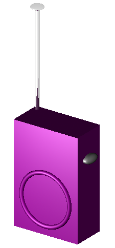
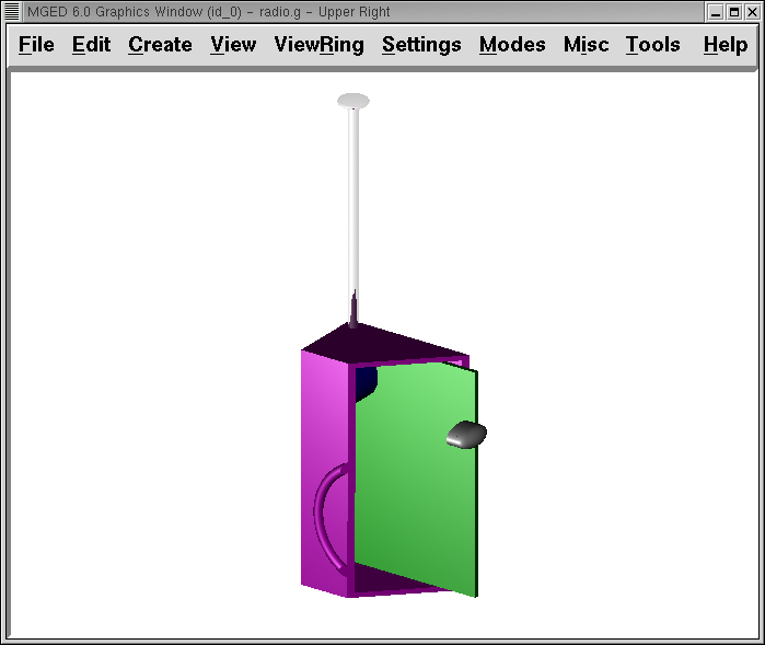
In Lesson 2, we made the basic shapes of a walkie-talkie radio to gain experience in viewing objects. Now that we have successfully modeled a few simple objects, let’s return to the radio to make it more realistic and, in so doing, discuss logical techniques and structures in modeling. When finished, our radio should look as follows:
1. Making the Shapes into Regions
Open the database radio.g that you created in Lesson 2. In the Command Window, use the ls command to list all the contents of your radio. It should read as follows:
   ant.s btn.s knob.s
   body.s btn2.s spkr.s
Now what does this list really contain? Parts to a model radio? Not really. What the list actually comprises is just a collection of shapes (which we have hinted at by using a .s suffix) that (1) do not have material properties, and therefore (2) do not occupy space.
|
Remember, in |
So our first order of business is to identify the major parts of the radio so we can properly define the regions. So far, our choices are fairly simple. The radio basically consists of (1) a body, which houses the speaker and all of the internal parts; (2) an antenna; (3) a volume control knob, and (4) a talk button. These should be our four regions.
Most of these shapes were fairly straightforward to create, with each item consisting of just one or two primitive shapes. However, if we think of the radio as a real-world object, the body of the radio is actually more complex than just a solid box with a few shapes glued to its surface. (Remember that all objects are solid unless constructed to be otherwise.) Therefore, let’s start with the main component of the radio-the body.
2. The Body of the Radio
If we think about it, the body of a radio is actually a hollow case. So, the first thing we need to do is hollow out the case’s interior to make room for internal components. To do this, we can use the inside command to create a shape, which we’ll call cavity.s:
inside body.s cavity.s 1 1 1 1 1 1 Enter
Now, we’ll make a region called case.r and define it as what’s left of body.s after cavity.s has been subtracted out. The command should look like this:
r case.r u body.s - cavity.s Enter
|
Remember that the inside command was originally created to hollow out objects such as gas tanks and boxes; however, it can also be used to create any new cutaway shape that has some relationship to a pre-existing shape. |
With our case now made, we can proceed to cut several holes through this structure to accommodate the antenna, the volume control knob, and the talk button. To do this, we must subtract the three shapes from the case as follows:
r case.r - ant.s - knob.s - btn.s Enter
Finally, we need to "glue" the lip around the speaker to the case’s front face by typing
r case.r u spkr.s Enter
Our body is now finished. Note that an experienced modeler would probably have combined the preceding three Boolean functions into a single command as follows:
r case.r u body.s - cavity.s - ant.s - knob.s - btn.s u spkr.s Enter
If we were to raytrace case.r at this point, we would see the following:
Note the hole for the antenna in the top of the case and the hole for the talk button on the side of the case. We will now fill these holes with their respective components.
|
Precedence Review The order in which these primitives were unioned and subtracted is important. We unioned in spkr. s last so that all the subtractions would apply to body.s. The rules of precedence for Boolean operators indicate that subtraction and intersection have a higher priority than union (meaning that they are performed first). Although the following operation is not in proper
Optionally, we could’ve unioned in spkr.s before body.s as follows:
Let’s consider, however, what would have happened if we had done the following:
In this last case, operator precedence would have caused the program to subtract cavity.s, ant.s, knob.s, and btn.s from spkr.s. Nothing would have been subtracted from body.s. Therefore, the holes in the case would not have been created. Subtracting cavity.s, ant.s, knobs, and btn.s from spkr.s would have produced no apparent effect because they do not overlap the volume of spkr.s. |
3. The Other Regions
Making the talk button is simpler than making the case. The button consists of the union of two primitive shapes. To make them into a region, type
r button.r u btn.s u btn2.s Enter
The volume knob and antenna are even simpler. They are single primitive shapes that can be made into regions by typing
r knob.r u knob.s Enter
r ant.r u ant.s Enter
4. Gathering the Regions into an Assembly Combination
Now let’s take all of the regions we have made so far and gather them into an assembly (or group) combination called radio.c so that we can keep all of these parts together. There are several ways to do this. One way would be to use a similar method to the one we used to make the regions:
comb radio.c u case.r u button.r u knob.r u ant.r Enter
A shortcut, however, would be to use the g (group) command as follows:
g radio.c case.r button.r knob.r ant.r Enter
Unlike the comb command, the g command assumes that all of the items specified will be unioned together, and so no Boolean operators need to be specified.
A final improvement would include using the database name wildcard *.r to quickly and easily specify all of the regions in the database:
g radio.c *.r Enter
If we now tree radio.c, we should get the following output in the Command Window.
   radio.c/
   u case.r/R
   u body.s
   - cavity.s
   - ant.s
   - knob.s
   - btn.s
   u spkr.s
   u button.r/R
   u btn.s
   u btn2.s
   u knob.r/R
   u knob.s
   u ant.r/R
   u ant.s
5. Assigning Material Properties to the Regions
Thus far, the objects we have created have no material properties
other than the gray plastic that MGED assigns by default to any
object without assigned material values. Now let’s improve our design
by assigning other material properties to the components.
We’ll give the antenna a realistic look by opening the Combination Editor, choosing ant.r from the drop-down Name menu, selecting mirror from the drop-down Shader menu, and clicking on Apply.
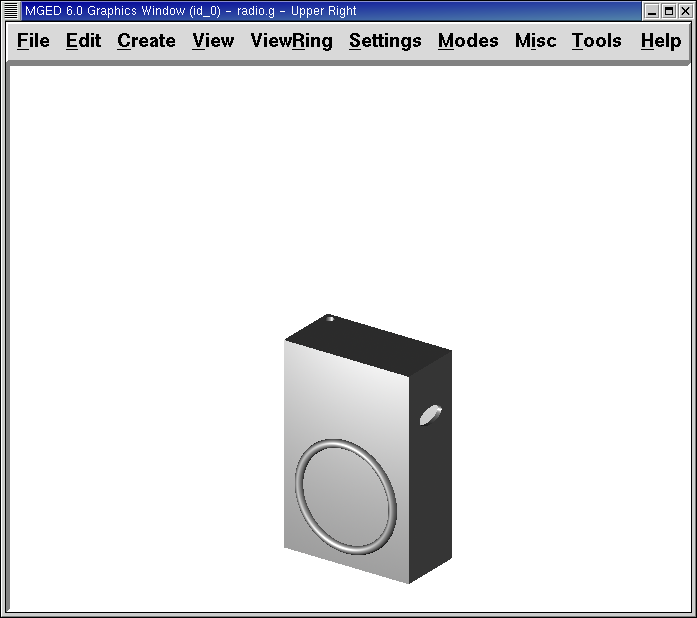
We’ll let the other components remain with the default plastic, but we’ll assign them different colors. With the Combination Editor still open, select case.r from the drop-down Name menu, select the magenta option from the drop-down Color menu, and then click Apply. Use the same method to assign the volume control knob (knob.r) a blue color. For the talk button (button.r), let’s keep it gray by leaving the default values in place. The design should appear similar to the following when raytraced in Underlay mode:
As we look at our radio now, we can see that the antenna looks a little bit like a straw. In reality, it should have a small cap on the end so that we can raise and lower the antenna. We can approximate this shape by creating an ellipsoid (which we’ll call ant2.s) and unioning it in with the rest of the antenna as follows:
in ant2.s ell1 2 2 94 0 0 1 3 Enter
r ant.r u ant2.s Enter
6. Adding Internal Components
Our radio is looking more and more realistic; however, it is still just a hollow shell. Let’s further improve it by making a circuit board to go inside the case. To do this, type:
in board.s rpp 3 4 1 31 1 47 Enter
r board.r u board.s Enter
Let’s give the board a green semi-shiny color. The easiest way to do this is via the Combination Editor, but this time let’s use the Command Line approach. Type:
mater board.r "plastic sh=4" 0 198 0 1 Enter
Diagrammed, this command says to:
| mater | board.r | "plastic sh=4" | 0 198 0 | 1 |
|---|---|---|---|---|
Assign material properties to |
the region called board.r. |
Apply the plastic shader with a shininess of 4 |
Give it a green color |
Inherit color material type |
Finally, we’ll include the board with the rest of the components in radio.c as follows:
g radio.c board.r Enter
Our radio should now look like the following:
In addition, the tree for radio.c should now look as follows:
   radio.c/
   u case.r/R
   u body.s
   - cavity.s
   - ant.s
   - knob.s
   - btn.s
   u spkr.s
   u button.r/R
   u btn.s
   u btn2.s
   u knob.r/R
   u knob.s
   u ant.r/R
   u ant.s
   u ant2.s
   u board.r/R
   u board.s
7. Making Specialty Models of the Radio
Now, what would happen to the circuit board if we were to raytrace the radio at this point? It would disappear because it lies within the case. So how can we make the circuit board visible outside of the case?
There are two common ways to do this: a transparent view and a cutaway view. Each method has its advantages and disadvantages. With the transparent view, the Boolean operations remain unchanged, but some of the material properties of the "outside shell" are altered to better view interior parts of the model. With the cutaway view, the material properties remain unchanged, but some of the Boolean operations are altered to remove parts of the model that are obstructing our view of other parts. We will try both ways to view the inside of our radio.
Different Approaches to Creating Specialty Models
An important point to note here is that the transparent and cutaway views are specialty models. They are similar in nature to items a manufacturer might make for special purposes. For example, an automobile manufacturer makes cars for everyday use, but also makes modified versions for display at certain events. The body panels might be replaced with a transparent material or be partially cut away to reveal interior components.
Good modeling practice follows the same pattern. The actual model of an item should not have to be changed in order to create a specialty view of it. Instead, a modified version of the item should be created. Thus, the modeler will not have to worry about remembering to return the model to the original condition after its special-purpose use, and the modeler can also retain the "display model" for future use.
There are two common approaches to making these specialty models: First, the modeler can copy the original and replace components with modified versions. Second, the modeler can create new, unique parts from scratch and construct the modified item. The method chosen is a matter of personal choice and is usually determined by the extent of the modifications being done and the complexity of the original object.
7.1. Transparent View
Making a specialty radio with a transparent case would probably be the easiest way to view the circuit board inside. All we have to do is make a copy of our present radio case and modify its material properties. We’ll call the specialty case case_clear.r. Type
cp case.r case_clear.r Enter
We can now use the Combination Editor to set the material properties on this case without affecting the "master" design of the radio. When this has been done, we can combine this modified case with the other unchanged radio components and group them as a new specialty radio named radio_clear.c.
To set the material properties of case_clear.r, choose plastic from the drop-down menu to the right of the Shader entry box in the Combination Editor. (Although this is the shader that is used by default, we want to explicitly select it in order to change one of its values.) Now change the Transparency of the case to a value of .8. Apply the change and close the Combination Editor.
Finally, create the specialty radio combination by typing:
g radio_clear.c case_clear.r button.r knob.r ant.r board.r Enter
and then Blast the display with
B radio_clear.c Enter
Now raytrace your design to view the resulting effect. The new transparent case should appear similar to the following:
As shown in the following tree diagram, the structure of this specialty radio_clear.c is not much different than that of the regular radio.c. The only difference is that case.c has been replaced with case_clear.c.
   radio_clear.c/
   u case_clear.r/R
   u body.s
   - cavity.s
   - ant.s
   - knob.s
   - btn.s
   u spkr.s
   u button.r/R
   u btn.s
   u btn2.s
   u knob.r/R
   u knob.s
   u ant.r/R
   u ant.s
   u ant2.s
   u board.r/R
   u board.s
|
Notice in the preceding figure that the color chosen for the transparent case does influence the appearance of the internal objects. Although we made the circuit board green, the filter effect of the transparent magenta case-which allows no green light to enter or exit the case-causes the board to appear to be dark purple. This is okay in our situation. However, if accuracy in color is important in a model, the modeler should remember to select a neutral color (such as white or light gray) for the transparent object. |
7.2. Cutaway View
Another way we can make the interior components of the radio visible is to create a cutaway view. Although it is a little more complex to make than the transparent view was, the cutaway view offers a particularly interesting way to view geometry.
There are several ways to make the cutaway view. Probably the easiest way is to use the "chainsaw" method to cut off part of the radio and reveal what is inside.
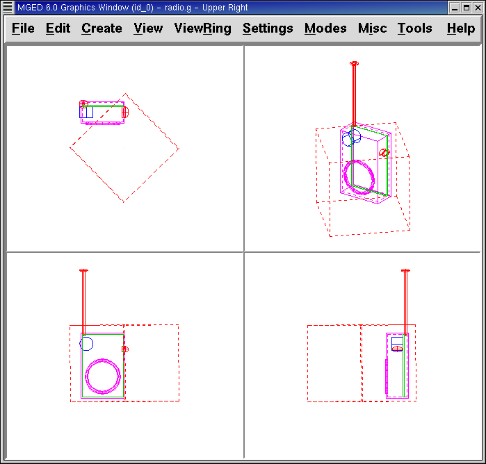
To do this, create an arb8 called cutaway.s, which will be used to cut off the front corner of the radio. Because this is a cutting shape (i.e., it is simply used to erase a portion of another shape and will not actually be viewed), the dimensions of the arb8 are not critical. The only concern is that cutaway.s be as tall as the case so that it completely removes a corner from it.
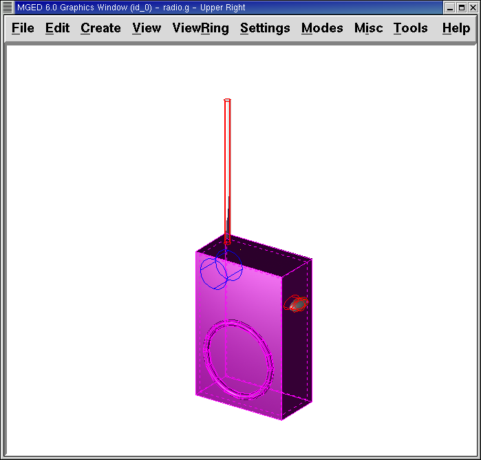
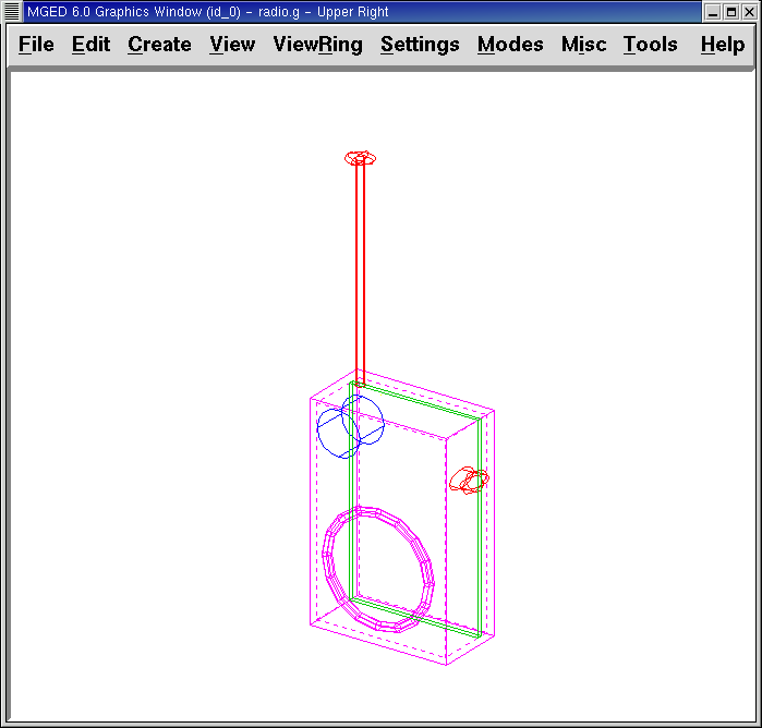
Use the Shift Grips and multiple views (especially the Top view) to align cutaway.s so that it angles diagonally across the top of the radio (as shown in the following wireframe representation). When you’ve aligned the shape the way you want it, create the following radio_cutaway.c combination that unions in radio.c and subtracts out the shape (cutaway.s) that is covering what you want to see (board.r):
comb radio_cutaway.c u radio.c - cutaway.s Enter
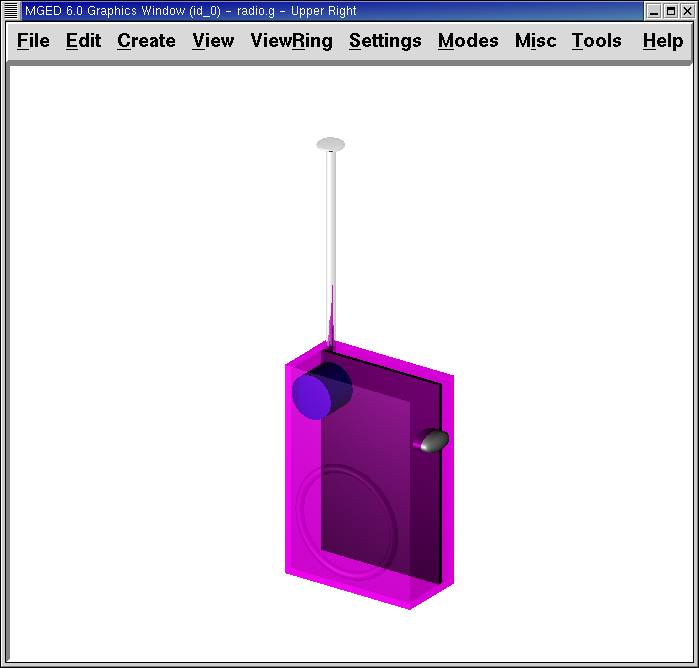
Blast the radio_cutaway.c combination onto the display and raytrace. Depending on how your arb8 intersected the radio, the cutaway should look similar to the following:
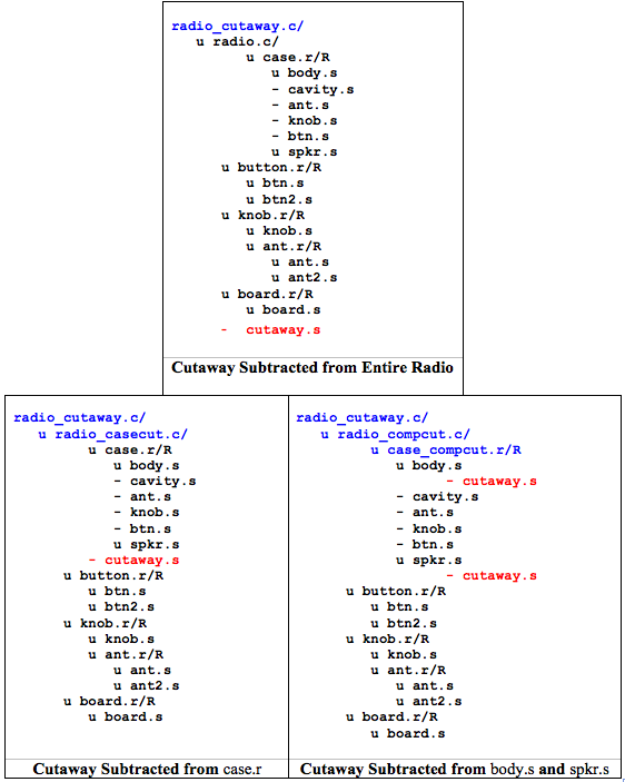
Notice in the preceding figures that cutaway.s removes everything it overlaps (including part of the circuit board). This is okay if we just want to see inside the case. However, if we want to see all of the circuit board and any other component overlapped by cutaway.s (e.g., button.r), we would have to adjust our Boolean operations a little so that the cutaway is subtracted only from our case.
To do this, we basically have two options: (1) we could move cutaway.s in the structure so that it is subtracted from only case.r, or (2) we could move cutaway.s in the structure so that it is subtracted from both body.s and spkr.s, the two components that make up case.r. While both of these options would produce the same effect, the first method requires just one subtraction, whereas the second method potentially provides more control by having the user select the individual components that will subtract out the cutting shape.
Take a minute and compare the following trees for the cutaways we have discussed so far. Especially note the position of cutaway.s in the different structures. Also, note that when cutaway.s was subtracted from a particular region or combination, the name of that region or combination was changed. The reasoning behind this goes back to our original discussion of specialty models. Remember that our purpose is to create a new special-purpose model, not change the existing model. So, we must change the name of any region or combination that contains any modified components or structures. If we don’t, the master model will also be changed.
8. Redefining the Structure of the Radio
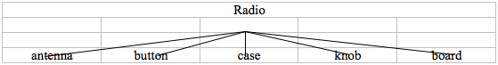
As shapes are added in a design, the modeler often finds that the structure or association of components needs to change. Thus, we should pause at this point and consider how our radio is structured. While there are many ways to structure a model, two common modeling categories are location and functionality. For our radio, we have so far grouped everything together under the general category of Radio, as shown in the following:
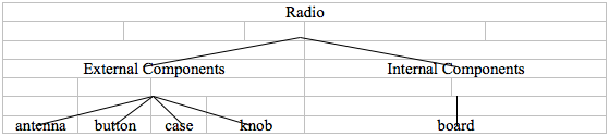
If we wanted to categorize our components according to location, however, we might structure the model as follows:
If we wanted to define our components according to functionality, we might structure the model another way. For instance, to repair an actual radio, we would open the case, take out the circuit board, fix it, and put it back in. When taking out the board, however, the knob and button would probably be attached to it in some way, and so they too would need to come out. Accordingly, our structure should be changed as shown in the following diagram to associate the knob and button with the circuit board.
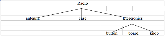
To accomplish this restructuring according to functionality, create an assembly called electronics.c to hold these components together. Type:
g electronics.c board.r knob.r button.r Enter
Of course, we now need to remove board.r, knob.r, and button.r from the radio.c assembly so that when electronics.c is added to the radio.c assembly, we won’t have the knob and button included twice in the model. To do this, use the rm (remove) command:
rm radio.c board.r knob.r button.r Enter
and then union in the electronics assembly:
g radio.c electronics.c Enter
Now the tree for radio.c should appear as follows:
   radio.c/
   u case.r/R
   u body.s
   - cavity.s
   - ant.s
   - knob.s
   - btn.s
   u spkr.s
   u ant.r/R
   u ant.s
   u ant2.s
   u electronics.c/
   u board.r/R
   u board.s
   u knob.r/R
   u knob.s
   u button.r/R
   u btn.s
   u btn2.s
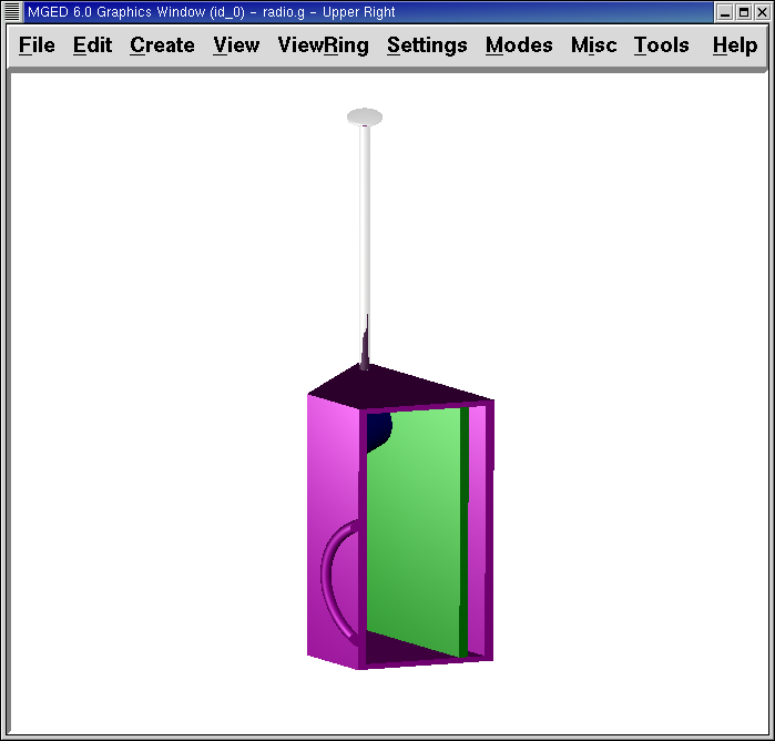
Now let’s remake our cutaway view. This time, let’s do what we discussed earlier and make the cutaway remove material from only the case, showing all the other components.
First, we need to get rid of the old radio_cutaway.c, which was based on our previous structure. To do this, type
kill radio_cutaway.c Enter
and then remake the combination by typing
comb radio_cutaway.c u case.r - cutaway.s u electronics.c u ant.r Enter
Now when we Blast the display and raytrace radio_cutaway.c, we should see the following:
9. Review
In this lesson, you:
-
Made the shapes of the walkie-talkie radio into regions.
-
Gathered the regions into an assembly combination.
-
Assigned material properties to the regions.
-
Added internal components to the radio.
-
Created specialty models of the radio.
-
Redefined the structure of the radio.