Annotations
Annotations
Annotations are currently created through the "in" command. Support for the annotation editor is yet to be provided. This primitive allows users to label models in the wireframe view. The primitive is aimed to be in the plane of the screen always, irrespective of the rotations. The annot object shown has the name annot_test. "get" and "l"(ell) commands give an overview of the structure. The input format can also be found below. Note that the second point that is entered by the user is relative to the first point. (This is done to make it easier, when the editor comes into place)
mged> in
Enter name of solid: annot_test
Enter solid type: annot
Enter the point to be annotated: 0
Enter Y: 0
Enter Z: 0
Enter the text label: (0,0,0)
Enter X,Y for the text placement: 3
Enter Y: 3
Enter the relative vertical position(1->bottom, 2->middle, 3->top): 3
Enter the relative horizontal position(1->right, 2->center, 3->left): 1
annot_test
Below is the get command
mged> get annot_test
result:
annotation
 V {0 0 0}
 VL { {3 3} {0 0} }
 SL { { line S 0 E 1 }
 { label (0,0,0) ref_pt 0 position top right } }
The l command (ell).
mged> l annot_test

annot_test:  2D annotations (annotation)
    V = (0 0 0)
    2 vertices
    Vertices:
     0-(3 3) 1-(0 0)

    Ant:
        Line segment (3 3) <-> (0 0)
        Reference point (3 3)
        Relative position: top right

    Label text: (0,0,0)
What we currently have is a foundation for the future work. Still, there are plenty of things to be done that will be accomplished with time.
Dimension Line
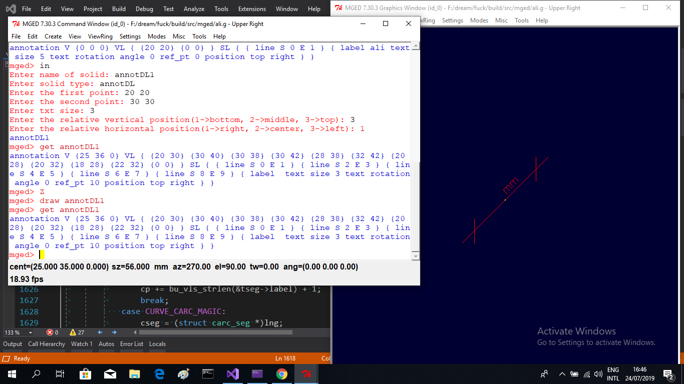
A dimension line annotation is suggested and not final yet, it is currently created through the "in" command. This capability is constructed using the same existing annotation primitive. it allows users to draw a dimension line between two points in the wireframe view. The lines that construct the dimension line is aimed to be in the model space, and the dimension line text will be always in the plane of the screen irrespective of the rotations and zooming . "get" and "l"(ell) commands give an overview about the structure. The input format can also be found below.
mged> in
Enter the name of solid: DL
Enter solid type: annotDL
Enter the first point: 20
Enter Y: 20
Enter the second point: 30
Enter Y: 30
Enter the text size: 3
Enter the relative vertical position(1->bottom, 2->middle, 3->top): 3
Enter the relative horizontal position(1->right, 2->center, 3->left): 1
DL
you can notice the get command in the picture.
What we currently have is a foundation for future work. the rotation angle of the text is calculated based on the coordinates of the first and the second points.
Label Box
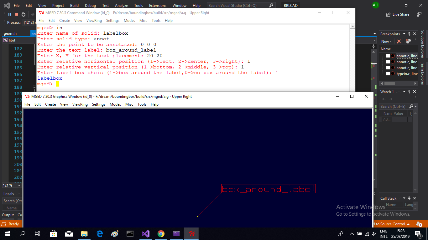
One feature of the annotations in the cad programs is having a box around the annotation text this isn’t final, it is work undergoing in GSoC 2019.
mged> in
Enter name of solid: labelbox
Enter solid type: annot
Enter the point to be annotated: 0
Enter Y: 0
Enter Z: 0
Enter the text label: box_around_label
Enter X,Y for the text placement: 20
Enter Y: 20
Enter the relative vertical position(1->bottom, 2->middle, 3->top): 1
Enter the relative horizontal position(1->right, 2->center, 3->left): 1
Enter label box chois (1->box around the label,0->no box around the label): 1
labelbox
this feature works also with all the position flags of the annotation.