The Overlap Tool
1. Introduction
The overlap tool is an MGED GUI intended to make it easier to visualize and resolve overlaps between regions.
The biggest assumption made by the overlap tool is that all matrices
in the database are identity (e.g. they’ve been pushed using the
xpush command).
2. Command Usage
2.1. Basic Steps to Launch the Overlaps Tool GUI
In the mged command window:
mged> overlaps_tool -F [.overlaps file]
2.2. Invocation Details
Running just overlaps_tool with no arguments launches the overlaps
menu GUI.
You can give the path of the .overlaps file as an argument if the database is in a different directory than the .ck results directory is in, or if you rename the database file after generating th results directory. This will cause the checker tool to get launched directly.
The -F option tells the tool it’s okay to make assumptions about
overlaps when doing subtractions (see subtraction assumptions).
2.4. New File
2.4.1. Create New Overlaps File
The Overlap File Tool is launched, which is used to create new overlaps file.
A tree of objects in the database is listed on the left hand side. Pressing the folder icon reveals the regions inside the objects. Double clicking on the items selects/deselects them.
The selected items are listed on the right hand side. Double clicking on the listed items deselects it.
There is also an option to manually type in the objects name to select/deselect them with add/remove buttons. The text entry also supports wildcards like * ? for batch operations.
Clicking on Check For Overlaps button, the tool runs check
overlaps at grid-size of 1024 from 16 different views (45 degree
steps in az and el directions) and then runs check overlaps
-g1mm,1mm, which runs it for three views at 1mm grid spacing.
The tool produces an output directory in the current directory (i.e. not the model directory unless it’s the same) named <model.g>.ck.
|
Running |
3. Using the geometry checker GUI
3.1. Bounding-Box Volume Calculation
When the geometry checker is run, the first thing that happens is the volume of the axis-aligned bounding box for each overlapping object is calculated. This can take several minutes depending on the size of the overlaps file.
When this finishes, the GUI window will populate.
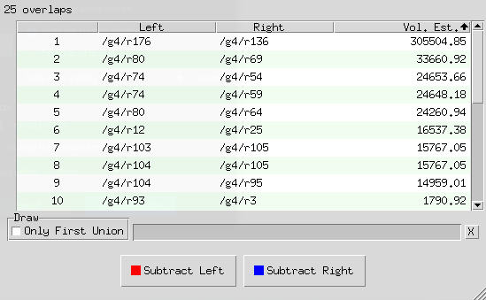
3.2. The Overlap List
The main element of the GUI is the overlap list, which consists of four columns. The first column on the left is just a reference number for the overlap.
The second and third columns are the paths of the overlapping regions. The region with the smaller bounding-box volume is always listed first, as the "Left" side of the overlapping pair.
The rightmost column is an estimate of the overlapping volume in mm3. This is not a separately calculated value, but rather an estimate derived from the overlap data. It’s not particularly accurate for any given overlap pair, but the relative relationship of the estimates is fairly accurate, so pairs with a higher volume estimate generally have a larger overlap volume than pairs with a lower volume estimate.
By default, the overlap list is sorted by highest volume estimate first, but you can click any of the headers to sort ascending/descending by overlap number, left or right path name, or volume estimate.
3.3. Drawing Overlap Paths
Clicking on an overlap will cause the left and right paths to be drawn as wireframes in the display window. The wireframes are colored red and blue respectively (matching the subtraction buttons at the bottom of the window).
Below the overlap list is an option to draw only the first unioned
solid in the region instead of the whole region. It’s enabled
automatically when using the -F option, because it shows just the
two objects the -F mode assumes to be responsible for the overlap.
However, this display option can be toggled whether you’re using -F
or not.
To navigate through overlaps you can:
-
Use the up/down keyboard keys to draw each overlap in turn.
-
Use the scroll bar on the right side of the overlap list to find a specific overlap.
-
Use the Home and End keyboard keys to scroll all the way to the top or bottom of the list.
If you shift-select multiple paths, all those paths are drawn. For large regions, it can take a while for all paths to be drawn. There’s a progress bar below the overlap list that shows how many of the selected paths have been drawn. The specific region being drawn appears above the progress bar.
The "X" button to the right of the progress bar can be pressed at any time during drawing to stop any more regions from being drawn. On a shift-select, there’s a short pause (about three seconds) before any drawing begins so you can hit the X button and prevent anything from being drawn at all.
3.4. Marking Overlaps
You can right-click on selected overlaps and chose "Mark Selected" or "Unmark Selected" to indicate which overlap pairs you have reviewed or attempted a fix on.
Marked overlaps are grayed out and moved to the bottom of the overlap list. The marked and unmarked sections independently maintain the current sorting of the overlap list.
These markings are saved to the .ck directory, so they are maintained when you close and reopen MGED.
3.5. Automatic Subtraction
For each pair of overlapping objects, the overlap GUI can automatically rewrite the tree of one side of the pair to subtract the other side to attempt to resolve the overlap.
Once you select one or more unmarked overlap pairs, the subtract buttons at the bottom of the window will enable and you can choose to subtract all the left-hand regions from the right-hand ones or vice versa.
Each pair that’s processed will be automatically marked in the overlap list.
The progress bar and X button work the same for subtractions as for drawing.
|
Performing many subtractions at the same time can take a while and if MGED is killed for some reason (e.g. system restart), the overlap tool isn’t guaranteed to handle that situation gracefully. It may corrupt the region it’s currently re-writing or fail to mark a processed overlap pair. |
By default, the overlap GUI will refuse to subtract any combination that doesn’t reduce to a single solid. That’s because subtracting a non-trivial combination complicates the re-written tree, and can lead to cycles (a - b - a).
Providing the -F ("first") option to the overlaps_tool command
causes the overlap GUI to assume that the overlap between an
overlapping pair only involves the first unioned solid in their
respective trees. Subtracting a combination with the -F option
enabled results in just the first unioned solid of that combination
being subtracted from the first unioned solid in the other object’s
tree.
For example, if a overlaps b and they look like this:
a/R
  u adapter.s
  u alert.c
    u ac.s
  - ant.s

b/R
  u bottle.c
    u box.c
      u bend.s
  - blend.c
    u balance.s
Then subtracting b from a would rewrite a to:
a/R
  u adapter.s
  - bend.s
  u alert.c
    u ac.s
  - ant.s