4. Assigning Material Properties and Raytracing in MGED
In this lesson, you will:
-
Recall primitive shapes made previously.
-
Make a region of two primitive shapes.
-
Assign material properties to your primitive shapes from the Command Window.
-
Clear the Graphics Window and draw the new region.
-
Raytrace your design from the GUI.
-
Use the GUI to change layers of the Graphics Window.
-
Clear the Graphics Window after raytracing a model.
1. Opening the Database
To recall the primitive shapes made in the previous lesson, start
MGED and go to the File menu and select Open. A control panel
will appear with a list of folders and files. Select shapes.g and
Open. A new box will appear, and you should select OK.
You should now have two windows prominently displayed on your screen.
At the MGED prompt in the Command Window, type:
draw sph2.s rcc2.s Enter
2. Creating a Region
Before you can raytrace your design, you have to make a region of the
two shapes. A region is an object that has uniform material
properties. Most applications that use BRL-CAD models consider
regions as the basic components of the model. Regions are constructed
using the basic Boolean operations of union, intersection, and
subtraction, which are discussed in the next chapter.
At the MGED prompt, type:
r shapes2.r u sph2.s u rcc2.s Enter
|
Make sure you key in the information correctly before you press ENTER. Spaces, or the lack thereof, are important. |
This command tells MGED to:
| r | shapes2.r | u | sph2.s | u | rcc2.s |
|---|---|---|---|---|---|
Make a region |
Name it shapes2.r |
Add the volume of the shape |
sph2.s |
Add the volume of the shape |
rcc2.s |
3. Assigning Material Properties to a Region
Now type in:
mater shapes2.r Enter
MGED will respond with:
   shader=
   Shader? ('del' to delete, CR to skip)
Type in:
plastic Enter
MGED will ask:
   Color = (no color specified)
   Color R G B (0..255)? ('del' to delete, CR to skip)
Type in:
0 255 0 Enter
This will assign a light green color to the region. MGED will
now ask:
   Inherit = 0 lower nodes (towards leaves) override
   Inheritance (0/1)? (CR to skip)
Type:
0 Enter
When you have completed this set of commands, your Command Window should look like the following example:
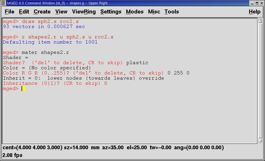
The one-line version of this set of commands would be:
mater shapes2.r plastic 0 255 0 0 Enter
Diagrammed, this command says to:
| mater | shapes2.r | plastic | 0 255 0 | 0 |
|---|---|---|---|---|
Assign material properties to: |
the region called shapes2.r |
Make the region of plastic |
Give it a color of light green |
Do not inherit colors or material type |
4. Clearing the Graphics Window and Drawing the New Region
An easy way to clear the Graphics Window of the old design and draw
the new region is to type at the MGED prompt:
B shapes2.r Enter
This command tells MGED to:
| B | shapes2.r |
|---|---|
Blast (clear) the Graphics Window and draw |
The region named shapes2.r |
The Blast command is shorthand for the combination of the Z and draw commands.
5. Raytracing Your Model
Now go to the File menu and select Raytrace. A dialog box called the Raytrace Control Panel will appear. At the top are menus for Framebuffer and Objects. Select Framebuffer. A drop-down menu will appear with six choices: Active, All, Rectangle Area, Overlay, Interlay, and Underlay. Make sure the Active, All, and Underlay options are activated (as shown by the presence of a red indicator to the left of each choice). Select OK.
|
When you select Raytrace from this dialog window, you start an
auxiliary program (rt) of the |
Change the background color produced by the raytracer by selecting Background Color in the Raytrace Control Panel. A drop-down menu will appear with some predefined color choices plus a color tool. Select the white option. The select button should now appear white, in accordance with your selection.
Next select Raytrace from the four options along the bottom of the box. The Graphics Window should start changing, and you will soon see your design in shades of green with the wireframe superimposed on the design, as shown in the following example:

As we have seen, you can specify the background color for the raytraced image.
You can also fill the entire framebuffer with the background color. To do this, select the desired color and then click the fbclear (framebuffer clear) button at the bottom of the Raytrace Control Panel.
6. Changing Layers of the Graphics Window
The Graphics Window of MGED is used to display different types
of graphical information: 3D wireframes and 2D pixels (or
images). Conceptually, each type of data occupies a separate layer in
the display. The 3D wireframes occupy the wireframe layer, while the
2D pixels (images) occupy the framebuffer layer. These layers can be
thought of as transparencies, and the order in which they are stacked
and displayed can be changed.
As mentioned previously, there is a Framebuffer menu within the Raytrace Control Panel. At the top of this menu is a toggle button labeled Active. This turns the display of the framebuffer layer on and off. Near the bottom of the same menu are three radio buttons: Overlay, Interlay, and Underlay. When the underlay mode is selected, the pixel data are displayed under or behind the vector data. Conversely, when the overlay mode is selected, the pixel data are in front of the vector data. The interlay option is similar to the overlay mode. The subtle difference is an advanced topic not covered here.
|
Figure 3. Framebuffer in Underlay Mode
|
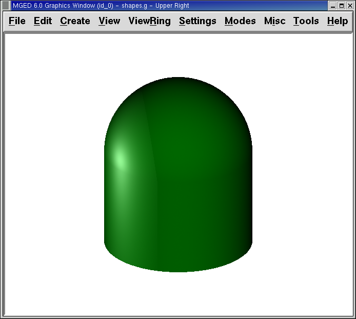
Figure 4. Framebuffer in Overlay Mode
|
To see how this works, go to the framebuffer menu and select Overlay. Notice that the wireframe representation disappears. Where does it go? If you answered "behind the framebuffer," you would be correct. To view the model’s geometry, you would have to make the framebuffer inactive or select underlay mode.
The wireframe layer has a yellow dot in the center that marks the
center of the view talked about in Lesson 2. This allows you to
determine whether the framebuffer is in overlay or underlay mode. If
you can see the yellow dot, the framebuffer is in underlay mode. If
you’ve told MGED to draw some geometry and the Graphics Window
seems to remain blank, you are probably seeing a blank framebuffer
masking the wireframe layer.
Note that you can change the view in the wireframe, but the view in the framebuffer does not automatically update to match. It is not possible to directly manipulate the view in the framebuffer. You must raytrace again in order to update the framebuffer image.
7. Clearing the Graphics Window
To completely clear the Graphics Window, you have to handle both the wireframe and framebuffer layers. Recall that you can clear the wireframe layer with the Z command. For the framebuffer layer, there is the fbclear button on the Raytrace Control Panel.
In some instances, you may prefer to turn off the framebuffer instead
of clearing it. When the framebuffer is turned off, MGED runs
faster because it doesn’t have to redraw the framebuffer each time it
updates the display. You can turn the framebuffer on and off by
toggling the Active item in the Raytrace Control Panel’s framebuffer
menu.
|
Note that in |
8. Review
In this lesson you:
-
Recalled primitive shapes made previously.
-
Made a region of two primitive shapes.
-
Assigned material properties to your primitive shapes from the Command Window.
-
Cleared the Graphics Window and draw the new region.
-
Raytraced your design from the GUI.
-
Used the GUI to change layers of the Graphics Window.
-
Cleared the Graphics Window after raytracing a model.