14. Gaining More Practice Placing Shapes in Space
In this lesson, you will:
-
Create copies of a shape using the Primitive Editor.
-
Draw a grid to help position objects.
-
Check the data tree and make corrections (if needed).
-
Assign material properties using the Combination Editor.
In previous lessons, we created and edited shapes and placed objects in 3-D space. This lesson provides more advanced practice in these areas using the candle design you created in the last lesson.
Open the candle.g database if it isn’t already open and draw candle1.c.
1. Making the First Sphere
Using the GUI, create a sphere named sph1.s. Go to the View menu and select Top view. Go to the Edit menu, select Scale, and size the sphere until it is proportionally about the same size as the one in the following illustration:
2. Using the Draw Grid Feature
Drag the sphere into position on the rcc, as shown in the previous illustration. To make this task a little easier, you can go to the Modes menu and select Draw Grid. This will create a grid overlay in the Graphics Window, which can help you position your spheres on the candle base.
3. Using the Multipane Feature
As discussed earlier, another feature that is available to help you position each sphere is the Multipane option under the Modes menu. This will allow you to see multiple views of the design you are creating.
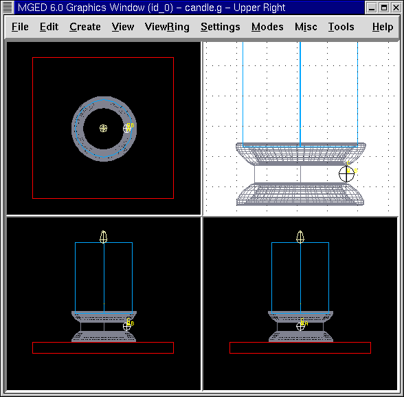
As you move a shape, the change in position will be reflected in each pane. The multipanes help you visualize where the shape is in 3-D space. In the default mode, the top left pane shows the top view, the top right pane shows the current view, the bottom left pane shows the front view, and the bottom right pane shows the left view. To turn off either the grid or the multipane functions, go back to Modes and select the feature you want to disable.
4. Creating Copies of a Shape
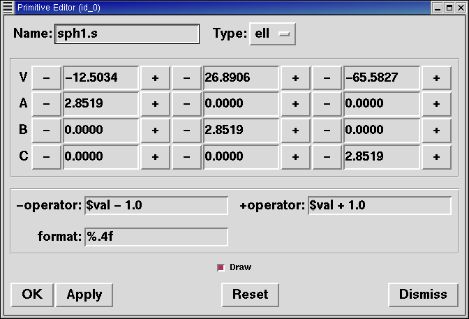
To make more jewels for the base, you could use the copy command on the Command Line (cp sph1.s sph2.s), but another way to do this is to go to the Edit menu and select Primitive Editor. Type sph1.s in the text box to the right of Name. Click on Reset and then change the name to sph2.s and click Apply. Continue doing this until you’ve made eight jewels. Because each of the new spheres is an exact copy of the first sphere, you won’t be able to see them until you select and then move them.
To position your new spheres, go to Primitive Selection. A submenu of shapes you have created will drop down. Use the scrollbar to the right of the list of shapes to access the spheres you have created, as shown in the following illustration.
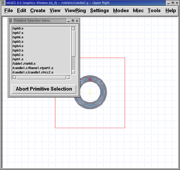
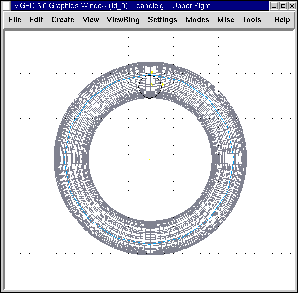
Click on sph2.s and drag it into position. Once you have positioned the eight spheres around the rcc, your design should look similar to the following ones when viewed from the top and front.
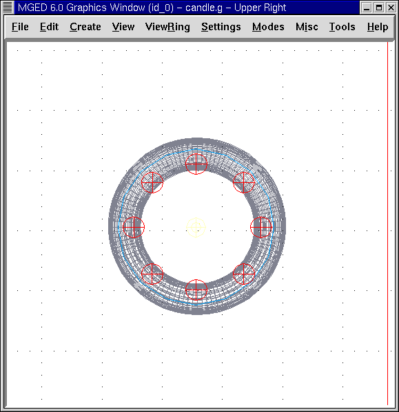
Figure 5. Candle from Top View
|
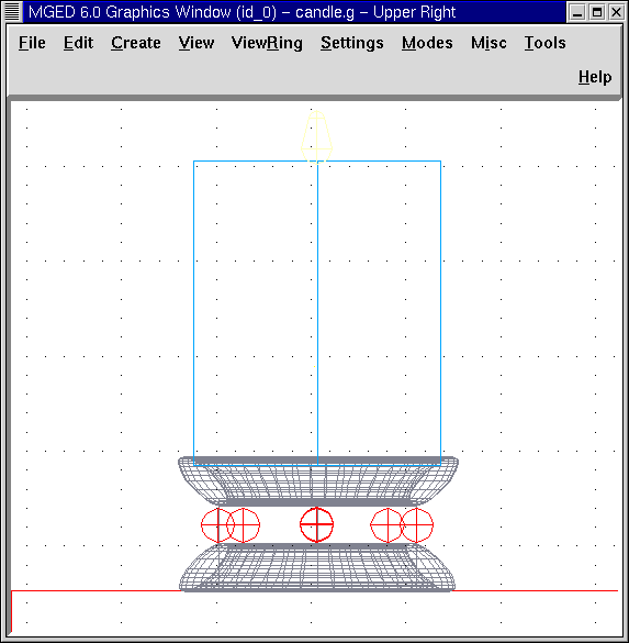
Figure 6. Candle from Front View
|
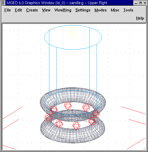
Notice from the front view that there appears to only be five spheres around the base of the candle, but there are eight spheres when you view the design from the top. That is because you are viewing 3-D space on a 2-D screen and the spheres in the back are behind the ones in the front. If you change the view to an az35, el25 view, all of the spheres will appear, as shown in the following figure. This is one reason why it is important to continually check your design from multiple views. A mistake in placement that doesn’t appear from one view may be very noticeable from another view.
5. Making Regions of the Spheres
Now that all your spheres are made and in place, it is time to make a region of each sphere. To do this, type the following in the Command Window:
r sph1.r u sph1.s Enter
r sph2.r u sph2.s Enter
r sph3.r u sph3.s Enter
r sph4.r u sph4.s Enter
r sph5.r u sph5.s Enter
r sph6.r u sph6.s Enter
r sph7.r u sph7.s Enter
r sph8.r u sph8.s Enter
|
There are three easier ways to make all of the regions. The first involves typing the first command:
and then using the up arrow to recall this command. Now use the left arrow to move backward in the Command Line to replace both occurrences of the number "1" with "2" and press ENTER. Repeat this for each of the numbers 3 through 8. The second approach is based upon the fact that the Command Line
interpreter of foreach i { 1 2 3 4 5 6 78 } { Enter
r sph$i.r u sph$i.s Enter
} Enter
This is much easier and faster than either of the previous methods. However, if there were many more spheres (say 1000 or more), then it might be easier to use a third approach, which employs a different loop type: for {set i 1} {i <= 1000} {incr i} { Enter
r sph$i.r u sph$i.s Enter
}
|
Next, go to Edit and then Combination Editor. Select sph1.r from the Select From All choice in the pull-down menu to the right of the Name entry box. Assign properties of plastic and the color red and then press Apply. We then can go back to the Select From All menu listing and repeat this process for the other seven spheres. Alternatively, we could use Apply after selecting the appropriate material properties and then type in the next sphere’s name; however, this method requires the user to remember to update the Boolean Expression box (e.g., change u sph1.s to u sph2.s) so that the Booleans for one shape are not applied to another shape.
|
Once again, we are performing the same operation multiple times. This is another good opportunity to use a loop. foreach i { 1 2 3 4 5 6 78 } { Enter
mater sph$i.r "plastic" 255 0 0 0 Enter
} Enter
In general, the graphical interface is good for doing one thing at a time or doing highly visual operations. Repetitive operations are best performed using a Command Line interface. |
6. Combining the Spheres with the Candle Base
We are now faced with an important decision. At the moment, the jewels overlap a portion of the candle base (specifically, the rcc1.s portion). Because two objects cannot occupy the same space, we must decide how to resolve this situation. There are two choices:
-
We can have perfectly round jewels with dents in the side of the candle base where the jewels are mounted.
-
We can have a perfectly round base with a cylindrical bite taken out of the back of each jewel.
For this lesson, we will use the first choice.
Now we are faced with a second decision: how to achieve this result. The key is that the space the jewels occupy must be subtracted from the correct part (rcc1.s) of the base.
On the Command Line, create rcc1.c by typing:
comb rcc1.c u rcc1.s - sph1.r - sph2.r - sph3.r - sph4.r - sph5.r - sph6.r - sph7.r - sph8.r Enter
Next, bring up the Combination Editor and select base1.r. Change the union of rcc1.s in the Boolean Expression window to a union of rcc1.c, and click OK. The tree of base1.r should now look like:
   u base1.r/R
     u eto1.s
     u rcc1.c
       u rcc1.s
       - sph1.r/R
         u sph1.s
       - sph2.r/R
         u sph2.s
       - sph3.r/R
         u sph3.s
       - sph4.r/R
         u sph4.s
       - sph5.r/R
         u sph5.s
       - sph6.r/R
         u sph6.s
       - sph7.r/R
         u sph7.s
       - sph8.r/R
         u sph8.s
     u eto2.s
     - rcc2.s
|
Note that we could have achieved the same results on the Command Line by using the rm (remove) command to remove rcc1.s from base1.r and then adding rcc1.c:
This would have resulted in a very similar tree as above: u base1.r/R
u eto1.s
u eto2.s
- rcc2.s
u rcc1.c
u rcc1.s
- sph1.r/R
u sph1.s
- sph2.r/R
u sph2.s
- sph3.r/R
u sph3.s
- sph4.r/R
u sph4.s
- sph5.r/R
u sph5.s
- sph6.r/R
u sph6.s
- sph7.r/R
u sph7.s
- sph8.r/R
u sph8.s
Finally, we could have avoided making an intermediate object in the database by moving rcc1.s to the end of the Boolean equation for base1.r and then subtracting each of the jewels from base1.r (hence, removing material from rcc1.s). This would have resulted in: u base1.r/R
u eto1.s
u eto2.s
- rcc2.s
u rcc1.s
- sph1.r/R
u sph1.s
- sph2.r/R
u sph2.s
- sph3.r/R
u sph3.s
- sph4.r/R
u sph4.s
- sph5.r/R
u sph5.s
- sph6.r/R
u sph6.s
- sph7.r/R
u sph7.s
- sph8.r/R
u sph8.s
It would be good practice to consider the relative merits of each of the approaches discussed. |
Now we need to add the jewels to the whole of candle1.c:
comb candle1.c u sph1.r u sph2.r u sph3.r u sph4.r u sph5.r u sph6.r u sph7.r u sph8.r Enter
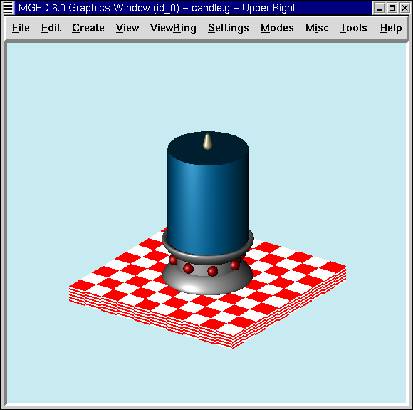
There are just a couple of things left to do before you raytrace your design. If you have enabled Multipanes or Draw Grid, go back to the Modes menu and disable them. Then, clear your screen and draw your new design by typing in the Command Window:
B candle1.c table1.r
Your new design should appear in the Graphics Window. Open the Raytrace Control Panel and select a pale blue color (200 236 242) by typing the three values in the Background Color entry box. When you raytrace your design, it should look similar to the following one: