13. Placing Shapes in 3-D Space
In this lesson, you will:
-
Create, edit, and place shapes in 3-D space.
-
Create custom colors using the Combination Editor.
-
Identify the attributes of the checker shader.
-
Identify how RGB colors are created.
In previous lessons, you created and edited shapes. You also placed objects in three-dimensional space. This lesson will provide more advanced practice on creating and editing shapes and placing them in 3-D space.
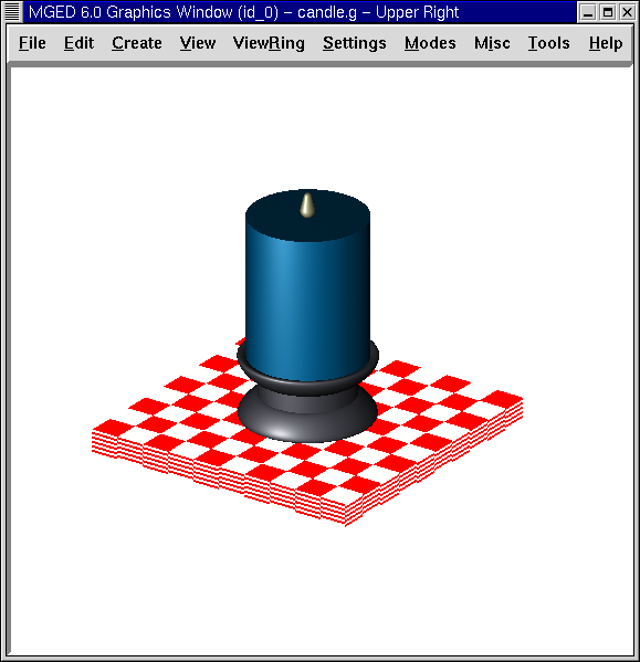
The design you will make in this lesson is a simple candle in a candle holder sitting on a table (as shown in the following figure). In the next lesson, you will add decorations and lighting to make the design more realistic.
Begin by creating a new database called candle.g. Title your database Candle Tutorial.
1. Creating the Tabletop
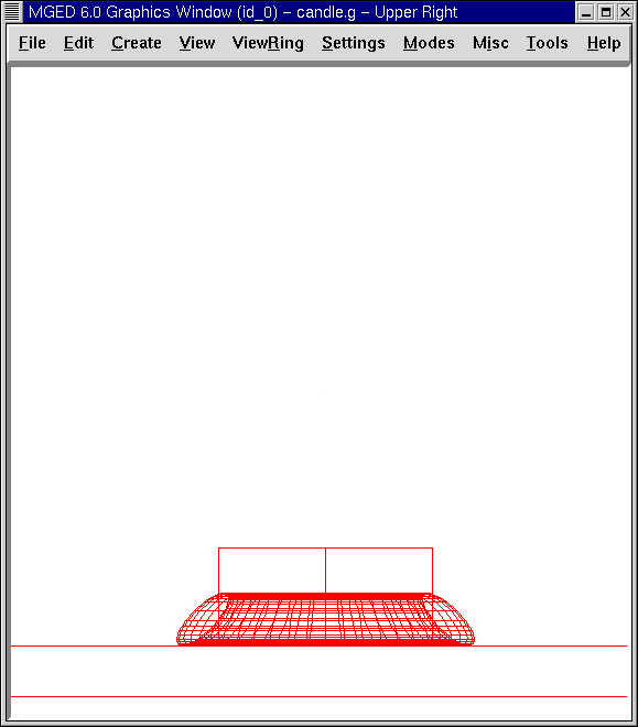
Create an arb8 from the GUI. Name the shape arb8.s. Go to View and select Front.
Go to the Edit option of the menu bar. The arb8 needs to be made larger, so, under the Edit menu, select Scale. Put the mouse pointer in the upper half of the screen to make the arb8 larger and click the middle mouse button until the sides of the arb8 touch each side of the screen. Use the SHIFT key and left mouse button to drag the arb into position, if necessary.
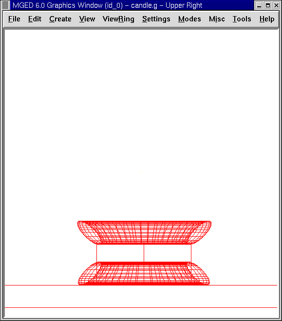
Under the Edit menu, select Move Faces and then Move Face 4378. Place the mouse pointer in the lower half of the screen and click the middle mouse button until the arb8 is about the thickness of a tabletop. Go back to the Edit menu and Accept the changes, and then use the SHIFT and any mouse key to position the tabletop so that it appears similar to the following:
Make a region of the tabletop by typing at the Command Window prompt:
r table1.r u arb8.s Enter
2. Creating the Candle Base
Create an eto and name it eto1.s. To create the bottom of the candle base, you will need to flip the eto 180'0. Type at the Command Window prompt:
rot 0 180 0 Enter
This tells MGED to rotate the shape 180'0 along the y axis.
Next, select Scale and make the eto a little smaller than its default
size. Place the eto on the tabletop by using the SHIFT key and left
mouse button to drag the base into position.
View your design from different angles to make sure the eto sits flush on the center of the tabletop. Select Accept when you are satisfied with its size and placement. Your base should be similar to the one shown as follows:

The next step in creating a candle base is to make a right circular cylinder (rcc). Name the shape rcc1.s.
Go to Edit. In addition to the standard commands, you will be presented with a menu of thirteen shape-specific ways to edit this shape.
Set H Set H (Move V) Set A Set B Set c Set d |
Set A,B Set C,D Set A,B,C,D Rotate H Rotate AxB Move End H(rt) Move End H |
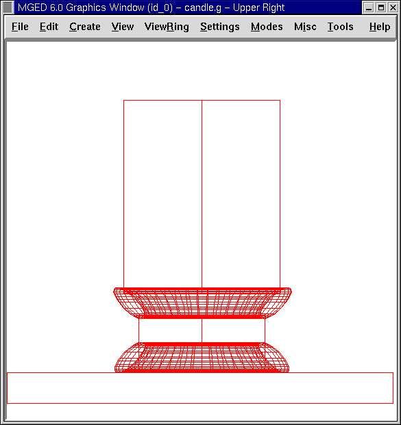
Scale the shape until it is slightly larger in diameter than the top of the eto1.s (you can check this by switching to a top view). Go back to Edit and select Set H. Reduce the height of the shape until the rcc is about two times the height of eto1.s. Position the cylinder on the candle-holder base. Check the placement of the rcc from the top, left, and front to ensure that it is centered in the eto. Make sure the bottom of the rcc is not quite touching the tabletop. Accept your changes. When done, your design should look like the following:
The last step in making the candle base is to create another eto. Name it eto2.s. Edit this shape as you did the previous eto and place it on top of the rcc, as shown in the following figure. Accept your changes when finished. Your candle base should now look like this:
Make a region of the three shapes of the base. Name it base1.r. Your Boolean expression should read:
r base1.r u eto1.s u rcc1.s u eto2.s
Note that we could have written it
r base1.r u eto1.s u eto2.s u rcc1.s
but the first expression is preferred to be consistent with the order of a later example. In a moment, we will want to remove some material that eto2.s gives us. By placing eto2.s last in the list, we can perform this removal easily.
3. Creating the Candle
Create an rcc and name it rcc2.s. Edit the shape as you did the previous rcc. When you are done, it should look similar to the one in the following illustration.
| After you have accepted the changes, you can get all of your tabletop and candle in the Graphics Window by using the SHIFT key and left mouse button to move your view of the design. |
Make a region of the candle. Your Boolean statement should read:
r candle1.r u rcc2.s
Now we create a cylindrical cutout in the base for the candle to sit in. To do this we can use the shape of the candle, as follows:
r base1.r - rcc2.s
Earlier we had mentioned that we would want to remove some material that we got from eto2.s. Now we have done it.
4. Creating the Candle Flame
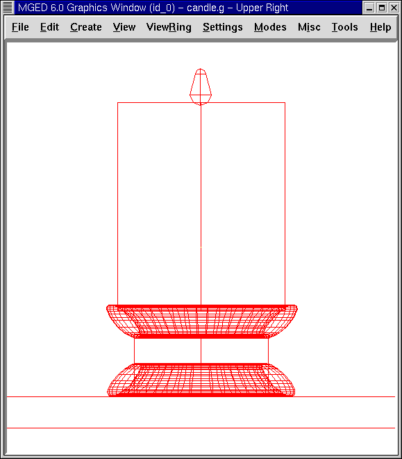
Create a particle (part) and name it part1.s. Edit and position the shape until your design looks like the following one:
Make a region of the flame by typing at the Command Window prompt:
r flame1.r u part1.s Enter
5. Making a Combination of the Base, Candle, and Flame
To make a combination of the parts of the candle, type at the Command Window prompt:
comb candle1.c u base1.r u candle1.r u flame1.r Enter
6. Checking the Data Tree
Now that you have made a number of regions and a combination, it would be a good time to check your data tree and make sure it agrees with the following tree. If you find that you have made a mistake in any of the parts of the tree, you can change them in the Boolean Expression box of the Combination Editor (refer to Lesson 5). At the Command Line prompt, type:
tree candle1.c Enter
Your Boolean expression should read:
   candle1.c/
   u base1.r/R
     u eto1.s
     u rcc1.s
     u eto2.s
     - rcc2.s
   u candle1.r/R
     u rcc2.s
   u flame1.r/R
     u part1.s
7. Assigning Material Properties to the Elements of the Design
To assign material properties to your design, go to the Edit menu and select the Combination Editor. Assign the following material properties to each of the elements:
| Element | Shader | Color(s) | Other |
|---|---|---|---|
Tabletop |
Checker |
Red (255 0 0); White (255 255 255) |
Scale (10) |
Candle Base |
Plastic |
Medium Gray (128 130 144) |
|
Candle |
Plastic |
Light Blue (0 166 255) |
|
Flame |
Plastic |
Light Yellow (255 255 190) |
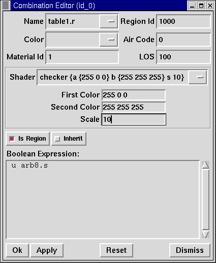
Notice that the checker shader for the tabletop includes two color values and a scale value. Type the values for red, white, and a scale of 10 in the boxes, as follows:
For the rest of the elements of the design, use the Color Tool to make the colors shown or simply type them in the Color text box, remembering to leave a space between each set of numbers.
|
As discussed previously, a color is made up of three numbers, ranging
from 0 to 255. The first number represents the amount of red, the
second represents the amount of green, and the third represents the
amount of blue used to make the color. A color of 0 0 0 is black, and
255 255 255 is white. This method of creating colors is different
from mixing pigment colors used in painting because you are dealing
with light. While it may seem strange at first, most |
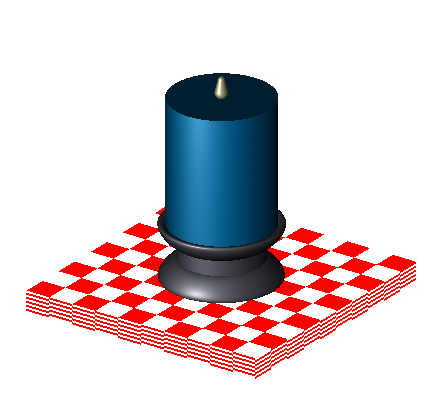
8. Raytracing Your Design
Before raytracing, change the View to az35, el25 to give a better view of the completed design and then Blast the old design by typing at the Command Window prompt:
B table1.r candle1.c Enter
This command tells the MGED program to:
| B | table1.r | candle1.c |
|---|---|---|
Clear the Graphics Window |
Draw the region named table1.r |
Draw the combination named candle1.c |
To provide the most light on your design, use a white background color. Your raytraced candle should look similar to the following: