Modeling Knight
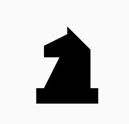
Last but not least, it is time to model the knight. I hope till now you are a little confident while working with dimensions because this section is going to have plenty of measurements.
Begin by creating a new database named knight.g.
The Knight piece can be broken down into four sections: base, body, neck and the top. Starting with the base which is same as the other pieces, type in the MGED command window:
in base.rcc rcc 0 0 0 0 0 1.1 2.25 ENTER
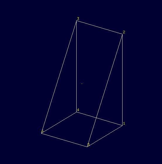
Now, coming to the body. The body section is made up of two shapes; arb6 and rpp. You are already familiar with rpp (Rectangular Parallelepiped), so let’s get you introduced with arb6 (Arbitrary Convex Polyhedron, 6pts) You will use a shape like the one given below:
While making this shape using the in command, MGED will ask you
to enter the values of all six points. The following image gives an
idea of the points:
You will use this shape to make the left part of the body section. To insert this shape, type:
in body1.arb6 arb6 ENTER
MGED will then ask you to enter x, y, z values of
all six points, one by one. Let’s understand each point and its value.
For point 1, type
0.65 0.5 1.1 ENTER
For point 2, type
0.65 0.5 2.9 ENTER
For point 3, type
0.65 -0.5 2.9 ENTER
For point 4, type
0.65 -0.5 1.1 ENTER
For point 5, type
1.75 0.5 1.1 ENTER
For point 6, type
1.75 -0.5 1.1 ENTER
Here,
-
1.75= radius of base.rcc (2.25) - the distance of the body from the edge of base (0.5) -
0.5= half of body’s width -
1.1= height of base.rcc -
2.9= height of base.rcc (1.1) + height of body (1.8)
To make the other part of the body, type:
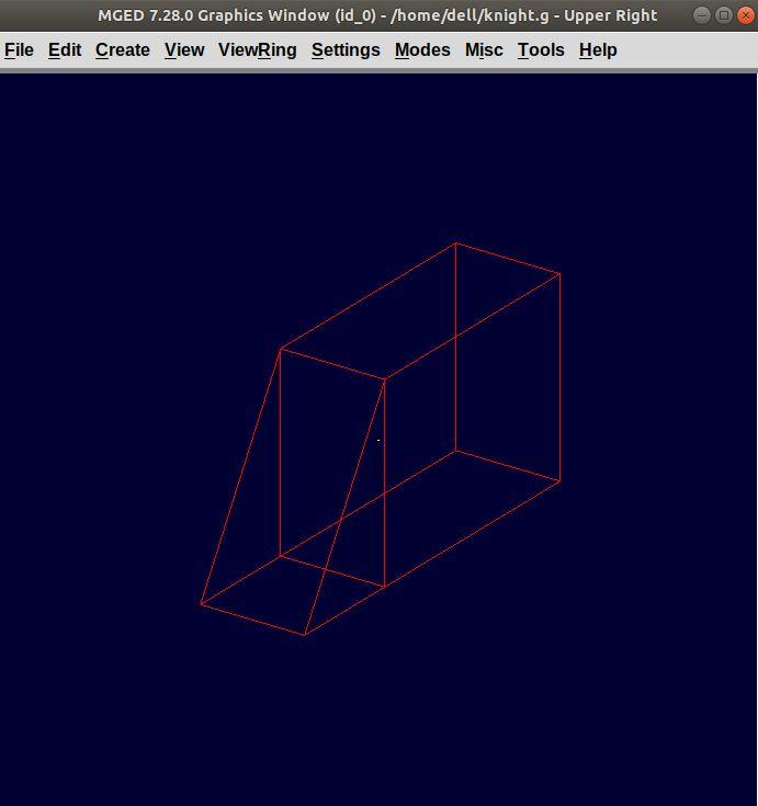
in body2.rpp rpp -1.75 0.65 -0.5 0.5 1.1 2.9 ENTER
This is what we get as output:
Moving on to the neck, it also consists of two parts. You will make two rpp. As you look at the target design, the left side of the neck has a slightly greater height than the right side. So, to make two rpp of different heights, type:
in neck1.rpp rpp 0 1.75 -0.5 0.5 2.9 3.7 ENTER
in neck2.rpp rpp -1.75 0 -0.5 0.5 2.9 3.4 ENTER
The top also has two parts, left and right arb6. The left one starts
from the top of neck1.rpp and the right one starts at the top of
neck2.rpp. Also, the right arb6 has a height slightly greater than
the left one. To get the shapes, type:
in top1.arb6 arb6 ENTER
0 0.5 3.7 ENTER
0 0.5 5.2 ENTER
0 -0.5 5.2 ENTER
0 -0.5 3.7 ENTER
1.75 0.5 3.7 ENTER
1.75 -0.5 3.7 ENTER
in top2.arb6 arb6 ENTER
-1.75 0.5 3.4 ENTER
0 0.5 5.4 ENTER
0 -0.5 5.4 ENTER
-1.75 -0.5 3.4 ENTER
0 0.5 3.4 ENTER
0 -0.5 3.4 ENTER
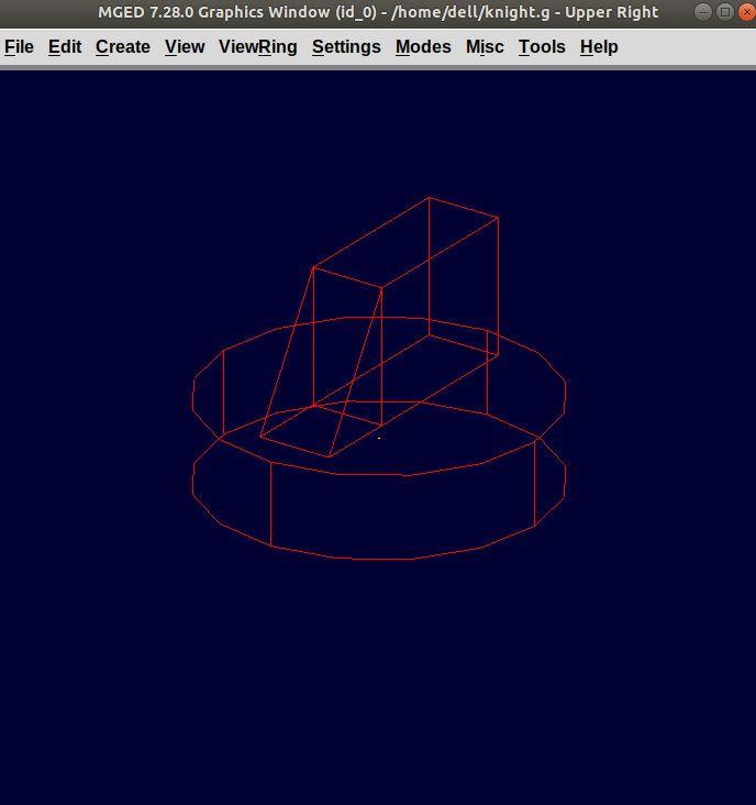
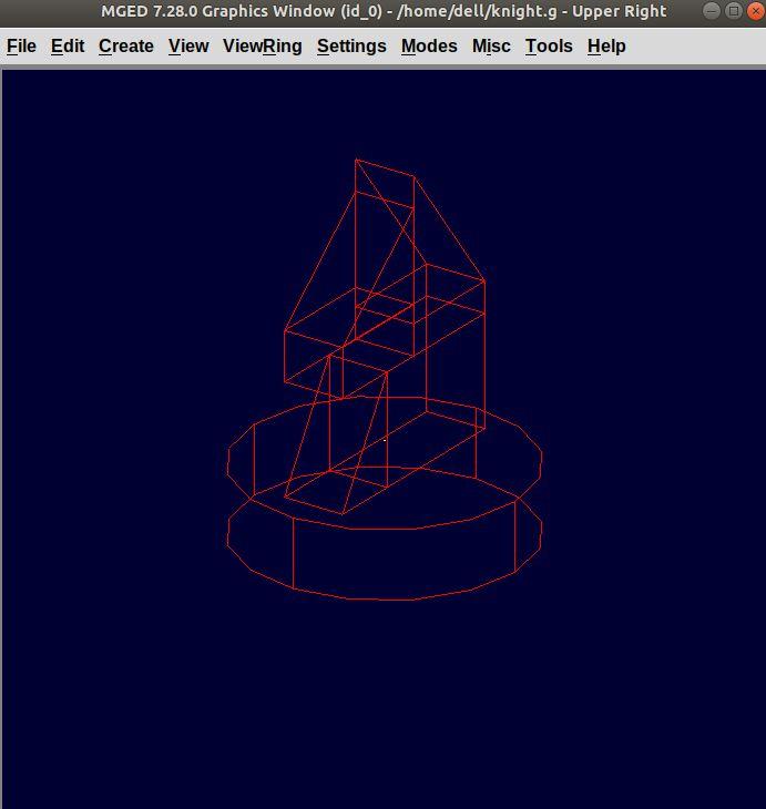
Our Graphics Window looks like this:
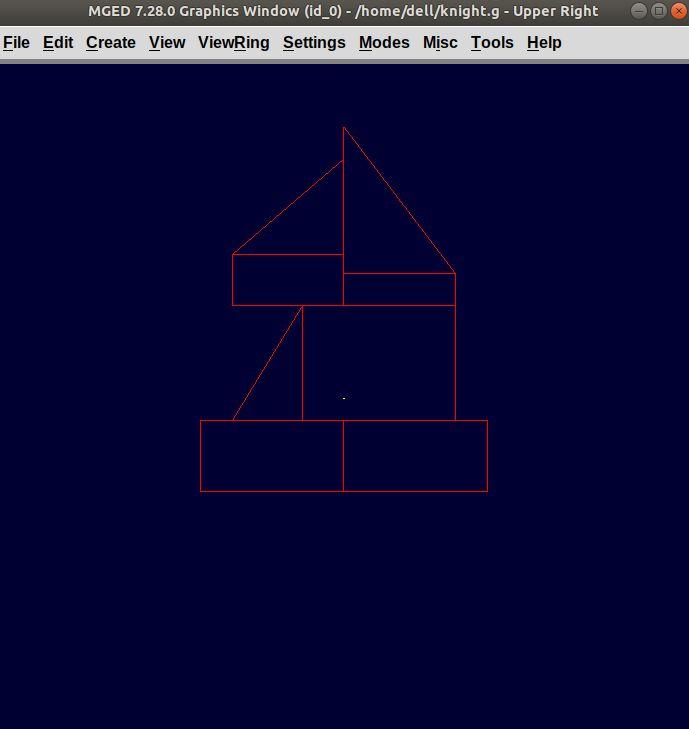
And in Left view:
Type the following command to make the region:
r knight.r u base.rcc u body1.arb6 u body2.rpp u neck1.rpp u
neck2.rpp u top1.arb6 u top2.arb6
ENTER
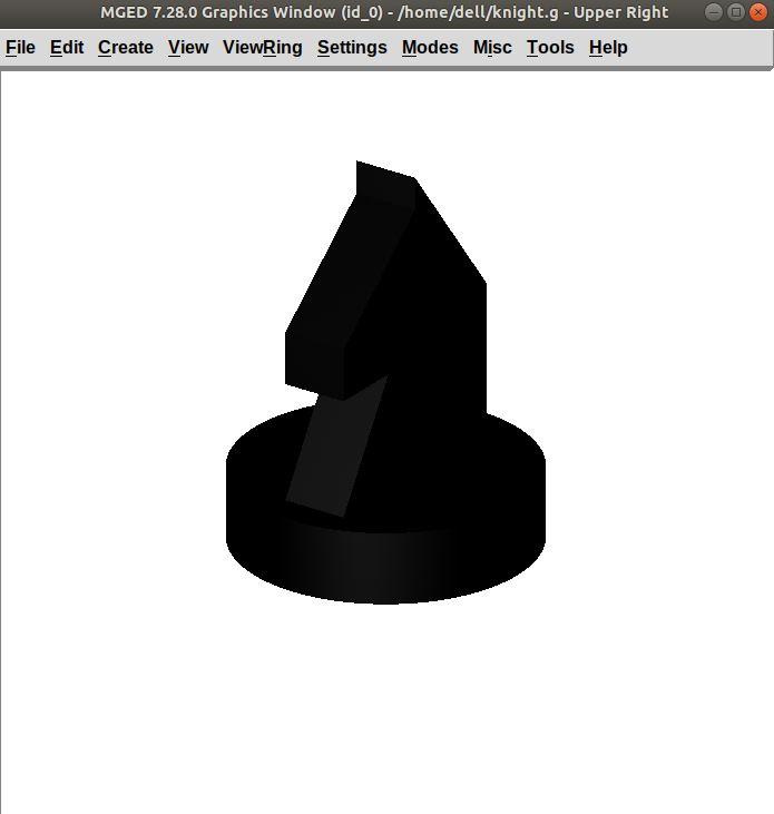
Now, assign the material properties to this knight and redraw your design. Type:
mater knight.r plastic 0 0 0 0 ENTER
B knight.r ENTER
After raytracing your design looks like:
In Left view:
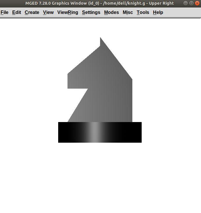
There is a color difference because the part above is plain and the bottom area is round.