Modeling Queen

As always, begin by creating a new database using the following command in the command prompt:
opendb queen.r ENTER
The King piece and the queen differ only in the top part. So, we will reuse the commands we used in the upper section. Type in the Command Window:
in base.rcc rcc 0 0 0 0 0 0.7 2.25 ENTER
in body.trc trc 0 0 0.7 0 0 2.2 2.25 0.85 ENTER
in curve.tor tor 0 0 2.9 0 0 1 3.2 2.4 ENTER
in neck.rcc rcc 0 0 2.9 0 0 0.5 1.4 ENTER
If you look closely, the only difference is the height of the
headmid.trc and the top section of the queen is a sphere. So, type:
in headbottom.trc trc 0 0 3.4 0 0 1.5 0.8 1.4 ENTER
in headmid.trc trc 0 0 4.9 0 0 0.6 1.4 0.6 ENTER
in headtop.sph sph 0 0 5.6 0.4 ENTER
The portion of the sphere at the top is slightly larger in size than a
semi-sphere. So, the vertex of the sphere is 0 0 0.5 i.e., vertex of
headmid.trc + height of headmid.trc + 0.1 . The value 0.1 is
added to make it slightly larger than a semi-sphere.
The output is:
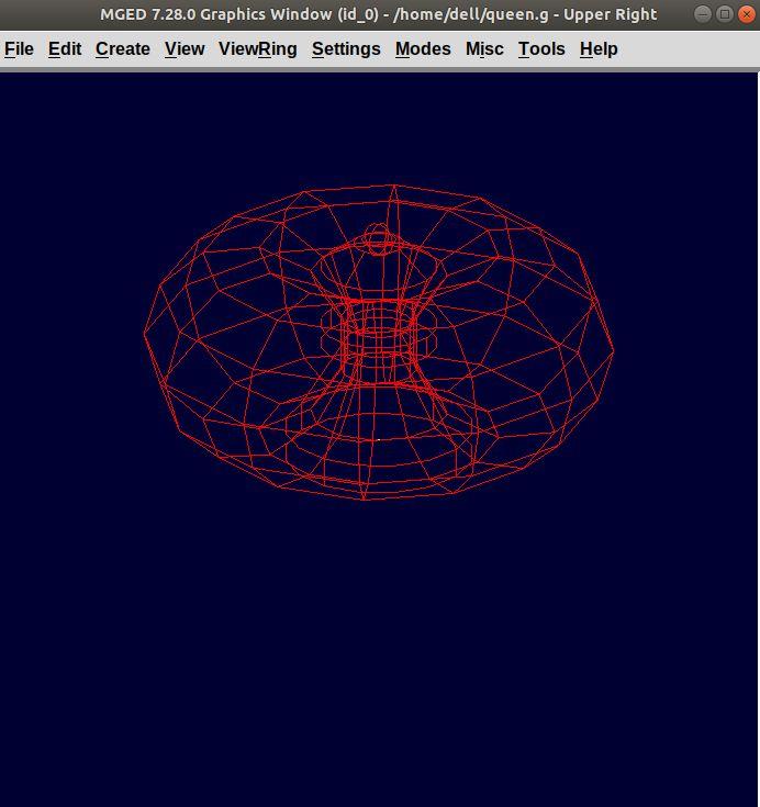
Make a region using the following command:
r queen.r u base.rcc u body.trc - curve.tor u neck.rcc u
headbottom.trc u headmid.trc u headtop.sph
ENTER
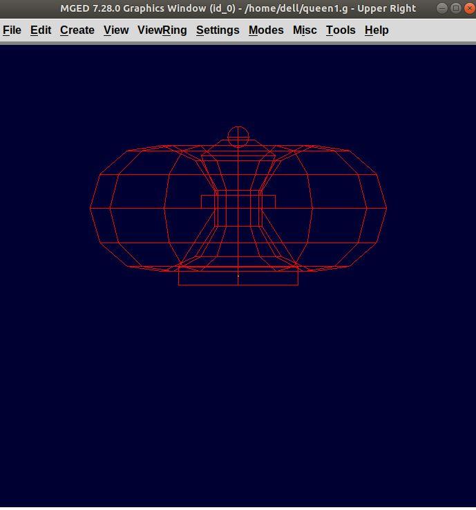
The front view looks like:
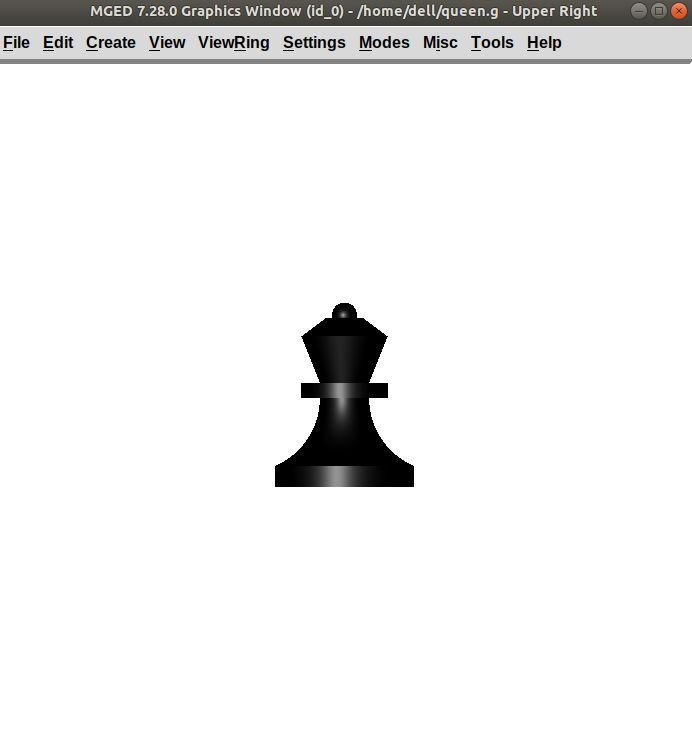
Now, comes the part of assigning the material properties and finally Raytracing the design. Type:
mater queen.r plastic 0 0 0 0 ENTER
B queen.r ENTER
After Raytracing, the queen in Front view looks like: