5. Evaluating Geometry
Evaluating geometry for correctness is an important companion to building real-world models. In fact, without testing the validity of the geometry’s positioning and composition, the modeling process has not actually been completed. Evaluation is performed at the following two times in the modeling process: (1) after individual objects are built and organized into regions and combinations, and (2) after the model is completely built. In both cases, the primary evaluation goal is to identify any errors in measurement, logic, or input that would make the model invalid or unrealistic.
One common error that the evaluation process reveals is overlapping geometry. Overlaps are the physical violation that occurs when two or more objects (regions) occupy the same volume in space. While this condition is occasionally acceptable (e.g., when modeling air volumes), it creates inaccuracies when the geometry is later analyzed.
|
Because all of the volume within a region is considered to be one material, it is acceptable for primitives within a region to "overlap" without error (e.g., spheres rounding cylinder ends). However, it is good modeling practice to minimize this wherever practical to simplify Boolean logic and keep primitives as compact as possible. |
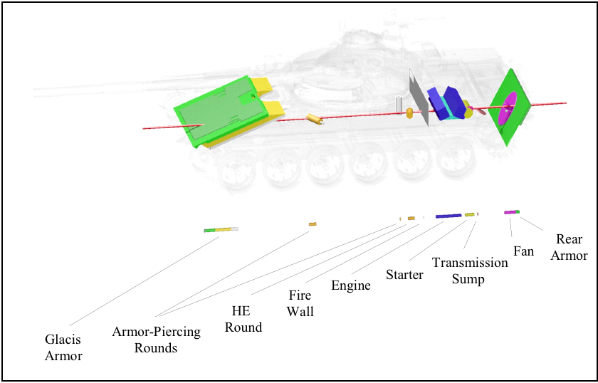
Shotlining is the principal method of interrogation in BRL-CAD. Rays are fired through geometry to report information about material properties, thickness, orientation, etc., of objects encountered along each ray’s path (see Figure 18).
There are several ways to evaluate BRL-CAD geometry. These include (1) rendering the image using rt, (2) checking for overlaps using rtcheck (or the lesser-known/used glint or MGED’s overlap tool), and (3) checking for faulty material composition (e.g., densities) using rtweight.
Generally, as soon as a region is completed, it is good practice to raytrace it using rt. This allows the user to visually verify that all Boolean logic is correct and that the geometry has no obvious problems. If there is anything questionable, it can then be examined more closely with a raytrace that highlights that particular area. Note that rendering is also a good way to compare geometry with drawings, sketches, photographs, or images from other CAD systems.
As subcomponents are organized into assemblies and the complexity of the geometry increases, it is then a good practice to use rtcheck (or glint or the overlap tool) to help find any errors in the geometry and isolate any problems.
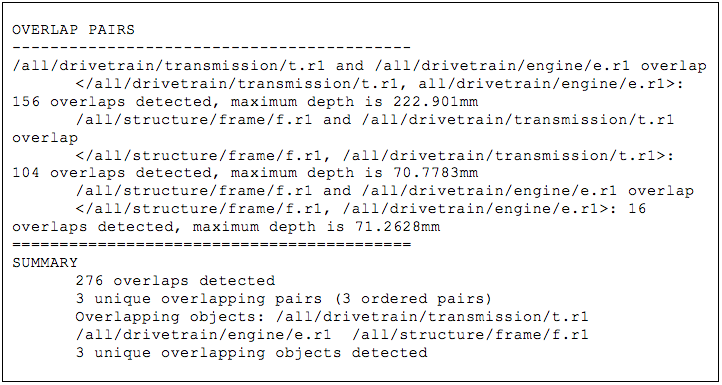
The rtcheck feature is a program run from the MGED command line or shell command line that fires a grid of rays through a list of objects in order to check for overlapping geometry. It reports a total count of the overlaps and a list of overlap pairs, a listing of the paths to the regions, the number of overlaps between each pair, and the maximum depth in millimeters. This is followed by a summary of the total number of overlaps, the number of unique overlapping region pairs, and a listing of all overlapping regions.
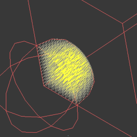
When run from within MGED, overlaps are displayed in the graphics display as yellow lines (see Figure 19). These yellow lines are created as temporary database objects and are stored in a combination called OVERLAPSffff00 ("ffff00" is hexadecimal notation for yellow [255 255 0]). Note that these temporary objects cannot be edited or saved and last only as long as they are not erased from the MGED display or are not overwritten by another set of overlaps.
After these lines have been created in the display, the user may use them as a visual reference to analyze the overlaps. A good practice is to erase geometry (e.g., the top-level item) and draw smaller subcomponents (perhaps just a few of the overlapping regions) to see more clearly where and what the problems are. When doing this, note that the zap (Z) and blast (B) commands should not be used until the evaluator is finished with the yellow lines as a visual reference. The user should also keep in mind that the rays are difficult to see from the azimuth/elevation orientation from which they were shot. To see them clearly, one should change the azimuth/elevation to another orientation.
To get the output shown in Figure 20, the "all" assembly was displayed in the graphics window and "rtcheck" was typed in the command window.
This command could also be run from outside of MGED. The command "rtcheck" is typed at a shell prompt, followed by the file name and the list of objects to be evaluated (in this case, "all"). Note that when running rtcheck from outside MGED, the default parameters include a top view and a grid size of 512 × 512 cells (which is the default size for all rt operations). For more details, see the on-line man page on rt.
|
When first checking larger assemblies, it is wise to use a relatively low-resolution rtcheck grid size—say, 128 × 128 pixels. Often, there are simple errors that produce large numbers of overlaps, and reporting them all takes a long time. Starting with low resolution, however, allows the user to quickly find and eliminate gross errors and proceed to the insidious small overlaps using a tighter grid and more specific view parameters. |
Another tool that can be useful for evaluating geometry, especially target descriptions, is rtweight. During or after model development, material codes and effective percentages can be assigned to the appropriate regions/ combinations based on the known materials and weights of actual components, subsystems, and systems. The rtweight feature can then be used to calculate volume and material densities and provide the overall weight of the model. This information can, in turn, be compared with the weight of the actual object to see if the two match. If they do not, chances are that there is a problem in the model’s material property assignments or construction (e.g., a hollow component was modeled as solid). For a list of standard material codes and air codes and their associated densities, see Robertson et al. (1996) and Winner et al. (2002).
In addition, the following are some general tips regarding the evaluation of geometry in BRL-CAD:
-
Evaluate early and often: As mentioned previously, evaluations should be performed both on individual objects as they are built and on sections of the model as they are assembled. In general, problems identified early are more easily isolated and fixed than if "buried" in a host of other problems. Early and continuous evaluation also reduces the amount of evaluation that needs to be done at the end. Final evaluation at the end helps ensure that the individual pieces are all working together in the model.
-
Evaluate at low resolution before high resolution: Especially in large and complex models, running rtcheck at high resolution can be computation- and time-intensive. Therefore, it is recommended that the modeler initially set a lower number of rays to be fired, fix any significant overlaps, and then increase the number of rays and/or zoom in on particular areas as fewer overlaps are found.
-
Use multiple views: Because rtcheck finds overlaps by firing individual rays at geometry, it can miss overlaps that occur between rays (e.g., when viewing a face edge-on or with low obliquity). Therefore, to ensure the highest evaluation accuracy possible, it is a good idea to use several of BRL-CAD’s standard views (e.g., top; az 35, el 25; etc.) as well as at least one arbitrary or randomly selected view (e.g., az 72, el 23).
-
Set the proper eye point: It is also possible for a user to miss detecting overlaps when the eye point is set in the middle or front of an object (e.g., when Z clipping is turned on). This does not mean that rtcheck is not catching them; it just means that they are not being displayed. So, before an evaluation is run, it is recommended that Z clipping be turned off and the eye point be sufficiently offset from the geometry so that the rays intersect the entire breadth of geometry or portion of geometry the modeler wants to evaluate and display.
-
Chunk big problems into smaller problems: Experienced modelers in BRL-CAD know that "killing" overlaps is simply a part of the modeling process. However, dealing with large amounts of overlaps can be overwhelming, especially to a new modeler or a modeler who has carefully built each piece and expects rtcheck to find few, if any, problems. Fortunately, in many cases, what appears to be extensive overlapping might just be one section of geometry (e.g., a wall of buttons and switches) that is slightly out of position, and a simple translation or rotation can simultaneously fix many problems. In other cases, overlaps are the result of simple miscalculations (e.g., a 2-in vs. a 1.5-in radius) that are not likely to be noticed until positioned with surrounding geometry. Whatever the case, the best approach to extensive overlaps is not to try to fix them all at once but to divide the problem into smaller problems, concentrate on individual pieces, and use the display to help identify and fix errors. For example, rather than starting with "all," start with, say, "engine," and then add "chassis." One can then continue this process and work up to evaluating the entire model.