2. The Model Process
1. The Importance of the Model Mission
The key to knowing how to build successful, effective models in BRL-CAD is to know why you are building them. Thus, before any measurements are taken, before any structures are laid out, and before any geometry is built, the modeler should, if possible, meet with program sponsors, participants, and/or end users to gain a clear understanding of the model’s intended purpose — that is, its mission.
Whether a model is intended for ballistic analyses, radar studies, or something else, the model’s mission should be the basis for determining how all parts of the modeling process should be conducted. This includes the level of detail that the modeler should achieve, the tree structure the model should have, the amount of modeling time that should be allotted, the types of validation and verification the model should have, and even the way documentation should be created and logged. This point may seem obvious, but failure to acknowledge the mission can result in wasted time and resources and, ultimately, an ineffective model.
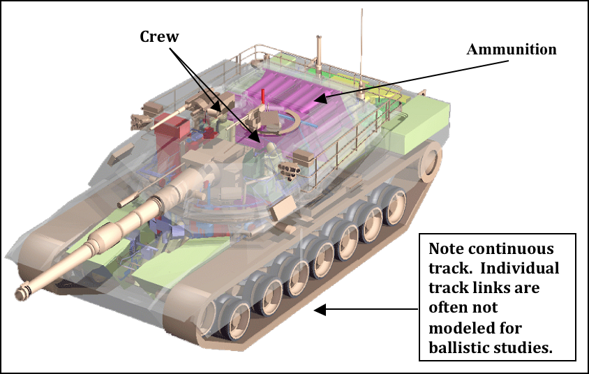
For example, if one is creating a geometric target description of a combat vehicle to simulate a ballistic penetration event, accurately modeled material thicknesses and densities of outside armor are crucial in analyzing penetration damage. In addition, it is usually important to include internal components such as fuel and electrical lines, ammunition, and even crew members, which can greatly affect the vehicle’s functionality if they are impacted by a projectile (see Figure 1).
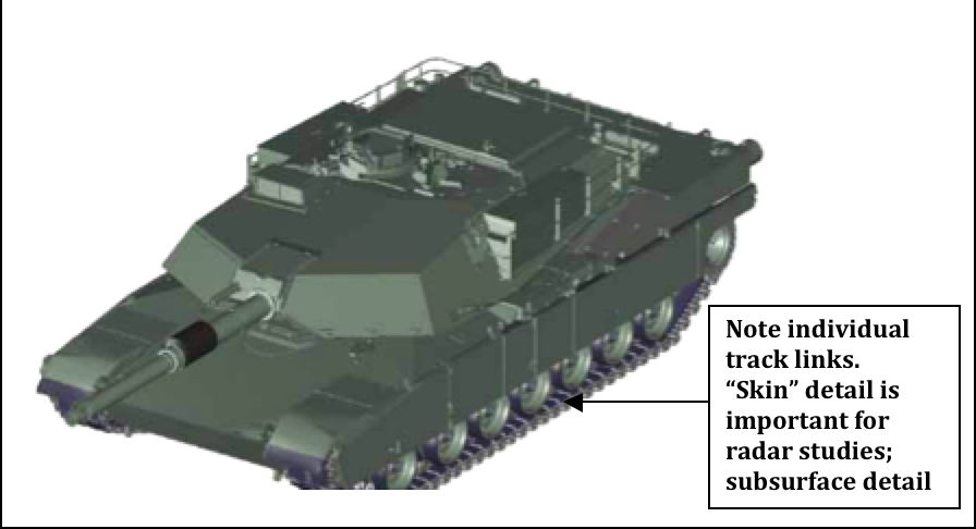
Radar signature studies, on the other hand, often call for a different type of model. For the most part, the vehicle’s outer shell — or "skin" — is what is important, and the previously mentioned armor thicknesses and internal components are usually unnecessary (see Figure 2).


It is also important to note that some models will need to serve multiple missions. If the modeler suspects that this will be the case with a model, it should be built to the highest level of detail that any of the intended users requires (and, of course, that time/resources permit).
2. M-O-D-E-L: A Five-Step Approach to Creating Effective Models
After one has explicitly and unequivocally established the "why" of a model, the "how" of a model can be addressed. Unfortunately, there is no single, universally accepted method to creating models in BRL-CAD. In fact, professional modelers are known to employ many unique techniques to accomplish equivalent results. Nonetheless, there are several basic steps or procedures that are commonly used by most modelers to create accurate, realistic, and useful geometric representations in a timely and efficient manner. These steps could be described in a variety of ways, but for convenience, they can be generalized into the following five categories and represented by the acronym M-O-D-E-L:
-
M-easuring (or collecting/converting) data,
-
O-rganizing the structure,
-
D-eveloping (or building) geometry,
-
E-valuating (or checking) geometry for correctness, and
-
L-ogging (or creating) documentation.
The remaining sections of this document address each of these steps in turn.
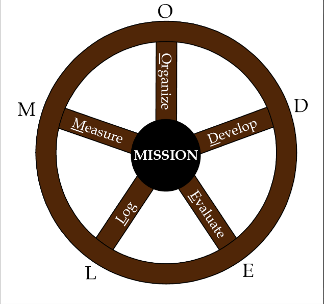
As shown in Figure 3, the modeling process can be thought of as a wagon wheel with five spokes. Each spoke extends out from the inner hub—the model’s mission—and is equally important in giving the wheel its strength and functionality. Also, although it is common to consider the steps in the order in which they are listed (i.e., M then O then D then E then L), the modeling process is dynamic, and it is not unusual for a particular phase to occur in a different order, to repeat itself, or to be skipped altogether as a project develops.

For example, the organization phase is often the first step in large or complex modeling projects because it helps the modeler establish a tree structure that will guide him in collecting/measuring the right (or right amount of) data. Also, the modeler often detects missing or inaccurate data in the geometry development phase, which requires a return to the measurement phase. Finally, in cases involving the conversion of geometry from another source, the measurement and development phases might be nonapplicable, and a modeler might skip directly to the evaluation phase.