6. Creating a Goblet
In this lesson, you will:
-
Create a new database.
-
Create, edit, and copy primitive shapes to make the parts of the goblet.
-
Make regions of the parts.
-
Make a combination of the regions.
-
View a data tree.
-
Raytrace your completed goblet.
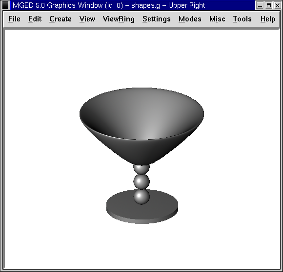
In this lesson, you will create a goblet similar to the one in the following example.
1. Creating a New Database
First, start MGED from the shell prompt. Select File from the
menu bar and then New. A dialog box will appear, and it will ask you
for a new database name. Type in goblet.g at the end of the path name
and select OK to create the new database. The program should tell you
that the database was successfully created and it is using millimeters
for its unit of measure.
2. Creating, Editing, and Copying the Parts of the Goblet
2.1. Creating the Goblet Base
Go to the menu bar, select the Cones and Cylinders category, and then select rcc for right circular cylinder. A dialog box will appear asking you to name the rcc. Type in base1.s and then select Apply (or press ENTER). A tall cylinder will appear in the Graphics Window that is ready for you to edit.
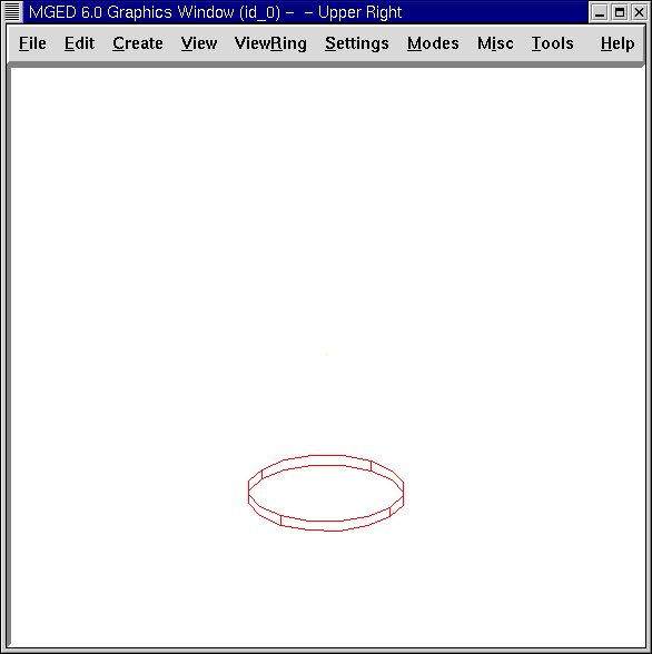
2.2. Editing the Base
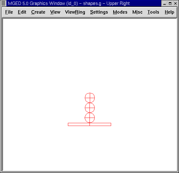
Go to the menu bar and select Edit and then Set H. Place the mouse pointer in the lower half of the Graphics Window and click on the middle mouse button several times. The cylinder will become shorter as you click. (Note that the closer your pointer is to the midpoint of the Graphics Window, the smaller the change will be. As you click farther away from the middle, the changes will be greater.) Continue clicking until the cylinder looks like a flat disk, as shown in the following figure. Click on Accept on the Edit menu when done.
2.3. Creating the Goblet Stem
Go to the menu bar, select Create, select Ellipsoids, and then select sph to create a sphere. You will be asked to provide a name for the sphere. Type ball1.s in the name box and then select Apply. A large sphere will appear in your Graphics Window.
Go to the Edit menu and select Scale. Place the mouse cursor/pointer in the lower half of the Graphics Window and click the middle mouse button until your sphere is about one-quarter the diameter of the base, as shown in the illustration that follows.
To move the ball on top of the goblet base, press the SHIFT key and left mouse button to drag the sphere into place. You can check your placement by going to the View option of the menu bar and selecting a Front view. In this view, you can align the center line of the sphere with the center line of the rcc. Repeat this process from a Left view. When you believe the sphere is correctly aligned with the rcc, go back to the Edit menu and select Accept.
2.4. Adding Additional Balls to the Goblet Stem
The next step is to add more spheres to your goblet stem. An easy way to do this is to go to the Edit menu and select Primitive Editor. A dialog box will appear. Enter the name for the first sphere you created, ball1.s. Next, select Reset (to reset the values of the dialog box to those of ball1.s) or hit return in the Name box. Again in the Name box, change ball1.s to ball2.s by using the BACKSPACE key to erase the 1. Type in a 2 and then select Apply.
Repeat this process with an sph named ball3.s. When you are done, select OK to close the Primitive Editor box. You now have three balls for your stem, but you won’t be able to see them until you edit them because they are in the same place.
An even easier way to make the copies is to use the cp (copy) command as follows:
cp ball1.s ball2.s Enter
cp ball1.s ball3.s Enter
2.5. Editing the Balls of the Goblet Stem
To edit the new balls you have created, go to the Edit menu and select Primitive Selection. A box will appear with the names of your base and balls. Double click on ball2.s to select it. You will see the first ball change color to white. Use the SHIFT key and any mouse button to drag this ball (which is really ball2.s) so that it rests on top of (and slightly overlaps) ball1.s . Check your views to align the ball as you did with the first ball. (Note that this alignment is even easier if you drag using the SHIFT and ALT keys and the right mouse button, which will constrain the movement of the ball to the Z direction.) Click on Accept under the Edit menu when finished.
If you were modeling a real goblet, you would want the balls of the stem to overlap slightly. If they barely touch, the stem would be very weak. If they do not touch, then the stem would be made of separate pieces of material suspended in space.
Repeat these steps to move ball3.s into position. When you are finished, your goblet should look as follows from a front view:
2.6. Making the Goblet Basin
The next step is to make the goblet’s basin. Go to the Create menu and select eto to create an elliptical torus. Name the torus basin1.s. Click on Apply. A large eto will appear in your Graphics Window.
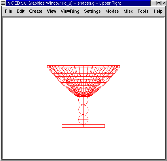
Go to the Edit menu and select Set C. Place the mouse arrow in the upper half of the Graphics Window and click on the middle mouse button until your eto is approximately the size of the one in the following figure. If you need to, use Scale to make the basin more proportional to the rest object and use the Shift Grips and multiple views to position the basin.
3. Making Regions of the Goblet’s Base, Stem, and Basin
In order for MGED to know what primitives to raytrace, you must
first designate these areas through Boolean operations. In this
example, the two Boolean operations used will be the union (u) and the
subtraction (-).
To make the stem a region, type at the Command Window prompt:
r stem1.r u ball1.s u ball2.s u ball3.s Enter
To make the base a region, type at the prompt:
r base1.r u base1.s - ball1.s Enter
To make the basin a region, type at the prompt:
r basin1.r u basin1.s - stem1.r Enter
Note that when creating base1.r, we subtracted a primitive shape from another primitive shape. When creating basin1.r, we subtracted an entire region from a primitive shape.
4. Making a Combination of the Regions
To combine all the regions into one object, you will need to perform one last Boolean operation. At the prompt in the Command Window, type:
comb goblet1.c u basin1.r u stem1.r u base1.r Enter
This operation tells the MGED program to:
| comb | goblet1.c | u | basin1.r | u | stem1.r | u | base1.r |
|---|---|---|---|---|---|---|---|
Make a combination |
Name it goblet1.c |
The combination will be made of a union of |
the region basin1.r |
and |
the region stem1.r |
and |
the region base1.r |
5. Viewing a Data Tree
MGED requires a certain logical order to the model data tree so
it knows how to raytrace the various elements. In the goblet, the
base and basin consist of regions composed of only one primitive shape
each. The stem, in contrast, consists of a region composed of the
union of three spheres. The three regions were combined to form a
complex object.
To view the data tree for this combination, type at the Command Window prompt:
tree goblet1.c Enter
MGED will respond with:
   goblet1.c/
   u basin1.r/R
   u basin1.s
   - stem1.r/R
   u ball1.s
   u ball2.s
   u ball3.s
   u stem1.r/R
   u ball1.s
   u ball2.s
   u ball3.s
   u base1.r/R
   u base1.s
   - ball1.s
The name of the overall combination of this design is goblet1.c. It is composed of the three regions: base1.r, stem1.r, and basin1.r. The region base1.r is composed of the primitive shape named base1.s minus ball1.s. The region stem1.r is composed of three primitive shapes named ball1.s, ball2.s, and ball3.s. The region basin1.r is composed of the primitive shape named basin1.s minus the region stem1.r.
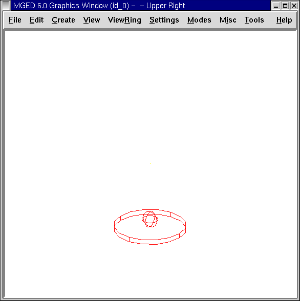
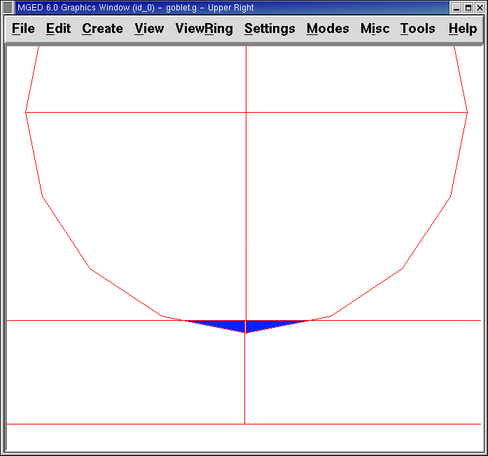
Remember that regions define volumes of uniform material. In the real
world (and in BRL-CAD), no two objects can occupy the same
space. If two regions occupy the same space, they are said to
overlap. To avoid having the base and stem overlap, we subtract
ball1.s from base1.s when we create base1.r. We also subtract the
stem1.r from basin1.s when we create basin1.r. This removes material
from one region that would otherwise create an overlap with another.
The following figure shows the overlap between ball1.s and base1.s in
blue.
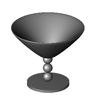
6. Raytracing the Goblet
To raytrace the goblet using the default material properties of gray plastic, go to the File menu and select Raytrace. When the Raytrace Control Panel appears, change the color of the background by clicking on the button to the right of the Background Color box and then clicking on the white option in the drop-down menu. Next, select Raytrace.
When you have finished viewing the goblet from the front view, go to the View option of the menu bar and select az35, el25 and then raytrace. If you want to view the goblet without the wireframe, go to the Framebuffer option of the Raytrace Control Panel and select Overlay. The goblet should look similar to the following illustration: