7. Assigning Material Properties to a Goblet
In this lesson, you will:
-
Review how to open an existing database.
-
Assign colors and the plastic shader to regions of the goblet.
-
Use the transparency and mirror reflectance options of the shader.
-
Raytrace various forms of your goblet.
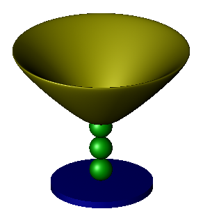
In this lesson, you will add material properties to the goblet you created in the previous lesson. The finished goblet should appear similar to the one in the following example.
1. Review of Opening an Existing Database
If you exited after the last lesson, open your goblet database
(goblet.g) again. The easiest way to do this is to open the database
from the Terminal Window when first starting MGED. To do
this, type at the prompt:
mged goblet.g Enter
Alternatively, you could start the MGED program, and select
File from the menu bar and then Open. A dialog box will appear and
ask you to enter an existing database name. Type in goblet.g (or
select it in the directory listing) and then select Open. The program
should tell you that the database was successfully opened and it is
using millimeters for its unit of measure. Click on OK.
2. Assigning Colors and the Plastic Shader to Regions of the Goblet
Go to the Edit menu and select Combination Editor. To select the various regions of the goblet you made in the last lesson, go back to the Name box and click the button to the right of the entry box. A submenu will appear. Double click on Select From All Regions. A list of regions created for this database will appear, including base1.r, basin1.r, and stem1.r. double click on base1.r to select that region.
Click on the button to the right of Color in the Combination Editor, and a drop-down menu will appear with a list of available colors along with a color tool that will let you create more colors. Click on blue. Next, click the button to the right of the shader box. A list of available shaders will appear. Click on plastic. A new set of options will appear. You will use two of these options in this lesson. Click on Apply to assign the color blue and the plastic shader to the goblet base.
Repeat this process to assign the color green and plastic shader to the stem1.r region and the color yellow and plastic shader to the basin1.r region. When you are finished, select OK to dismiss the Combination Editor box.
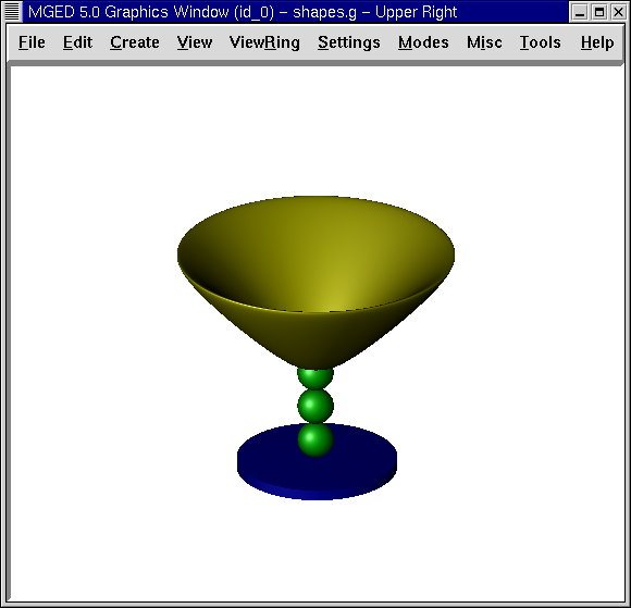
Although the changes have been made to the database, the display in the Graphics Window doesn’t reflect them yet. So, return the mouse pointer to the Command Window and type at the prompt:
B goblet1.c Enter
This command clears the screen and redraws the goblet with the color selections applied.
2.1. Raytracing the Goblet
To raytrace the goblet, go to the File menu and select Raytrace. The Raytrace Control Panel will appear. Move your mouse pointer to the button to the right of Background Color and select the white option. To make the raytracing go faster, you can resize the Graphics Window to make it smaller before you open the raytrace panel. When the window is resized, select Raytrace to start the raytrace process.
|
As mentioned previously, it is undesirable to have regions that overlap. Although having overlaps may not always affect the raytracing process, if the model were going to be statistically analyzed, overlaps would create problems. |
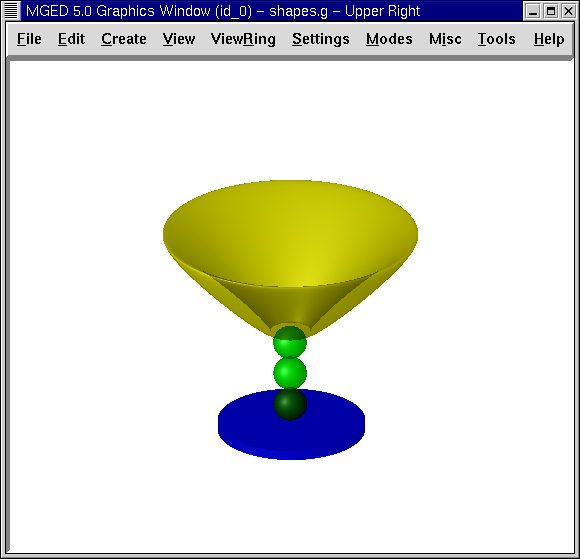
While the goblet is raytracing, move your mouse cursor to the Framebuffer option of the Raytrace Control Panel menu bar and select Overlay. When the raytrace process is finished, you should have a goblet similar to the following example:
3. Using the Transparency and Mirror Reflectance Shader Options
The raytraced goblet looks fairly realistic, but it could be enhanced by using other options of the Combination Editor. When you selected the plastic shader, a new set of options appeared, allowing you to choose various properties or attributes of the shader. Among the options was Transparency. You can adjust this property on individual regions by entering any value between 0.0 (opaque) and 1.0 (transparent).
Just as you applied color and a shader to each of the goblet’s three regions, you can adjust the transparency of each region by (1) selecting the region in the Combination Editor, (2) left clicking on the box next to Transparency, and (3) entering any value between 0.0 and 1.0.
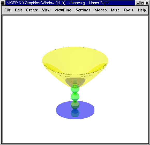
For this lesson, open the Combination Editor, click the button to the right of the Name box, choose Select From All Regions in the drop-down menu, and then choose the base1.r region. Make sure plastic is the shader selected and type in .5 to make your region semi-transparent. Click on Apply and repeat this process for each of the other two regions. Then Raytrace the goblet, which should look similar to the following:
The colors of the semi-transparent goblet are brighter than those of the opaque goblet because more light is allowed to penetrate the plastic material. You could make the goblet more realistic in appearance by returning to the Combination Editor and adding a Mirror Reflectance. For each region, place your mouse cursor in the box next to this option, click the left mouse button, and type in .45. This will cause about half of the available light to be reflected off the surface of the goblet.
4. Raytracing the New Forms of the Goblet
Click on Apply and Raytrace the design. The new image should appear similar to the following example:
The new image is substantially different in appearance from the original image. Continue changing the values of transparency and mirror reflectance to see how they impact the resulting image.
Remember that when using these options, the combined value of both options should be less than 1.0. The following table shows you just some of the many possible combinations you could use:
| Transparency Value | Mirror Reflectance Value |
|---|---|
.50 |
.49 |
.35 |
.64 |
.20 |
.57 |
.10 |
.89 |
.89 |
.10 |